
Heating cooker

Active Publication Date: 2017-12-21
PANASONIC INTELLECTUAL PROPERTY MANAGEMENT CO LTD
View PDF0 Cites 14 Cited by
  • Summary
  • Abstract
  • Description
  • Claims
  • Application Information

AI Technical Summary

Benefits of technology

The patent text describes two heating cookers and their limitations in cooking different sized materials. The technical effect of the patent is to provide a heating cooker that can cook both small and large materials more uniformly using a stirring function.

Problems solved by technology

However, as the heating proceeds, these cooking materials start to release moisture.
As a result, the same area of the cooking materials is continuously heated, thus resulting in uneven heating.

Method used


Image

  • Heating cooker
  • Heating cooker
  • Heating cooker

Examples


first exemplary embodiment

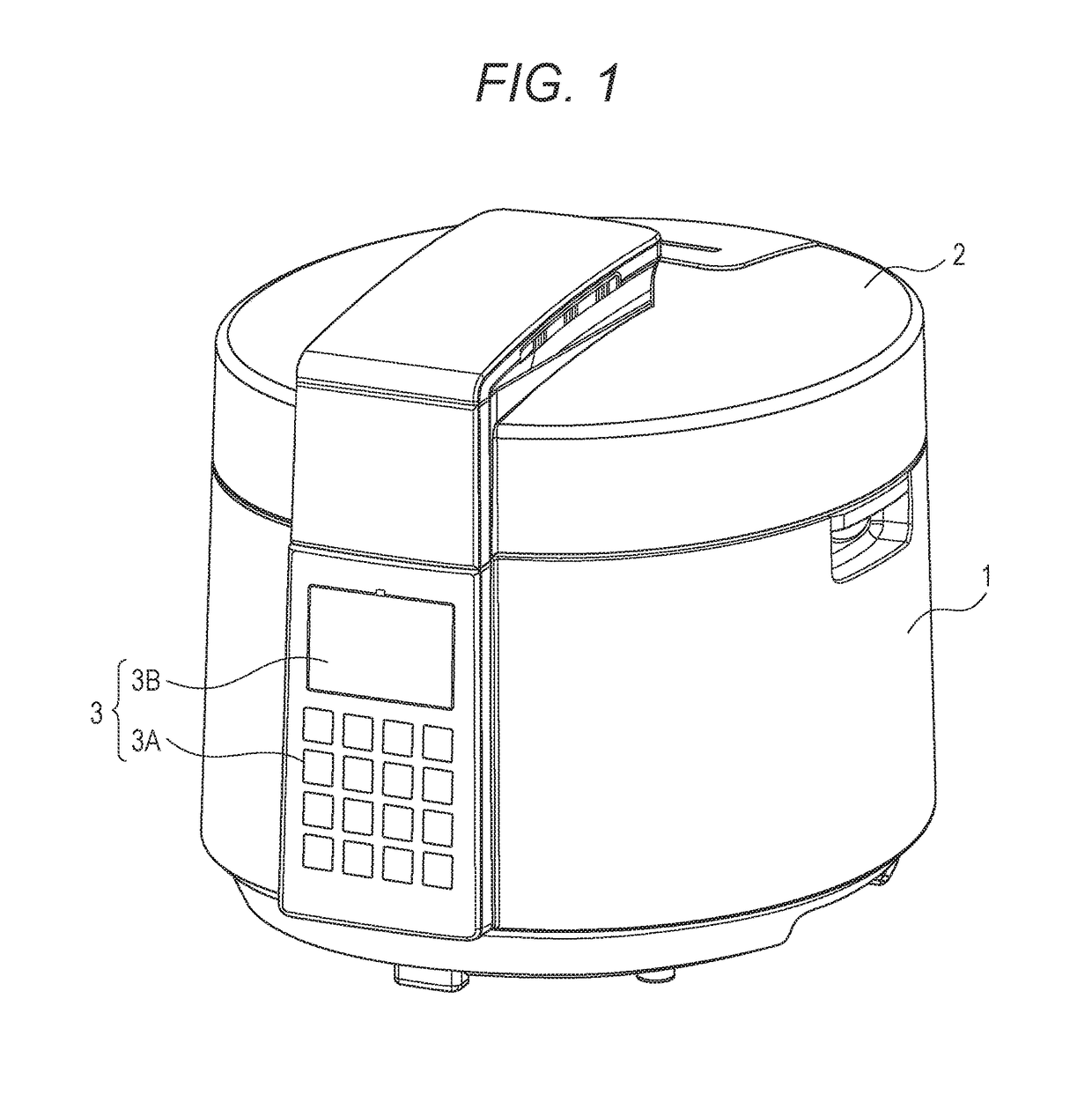
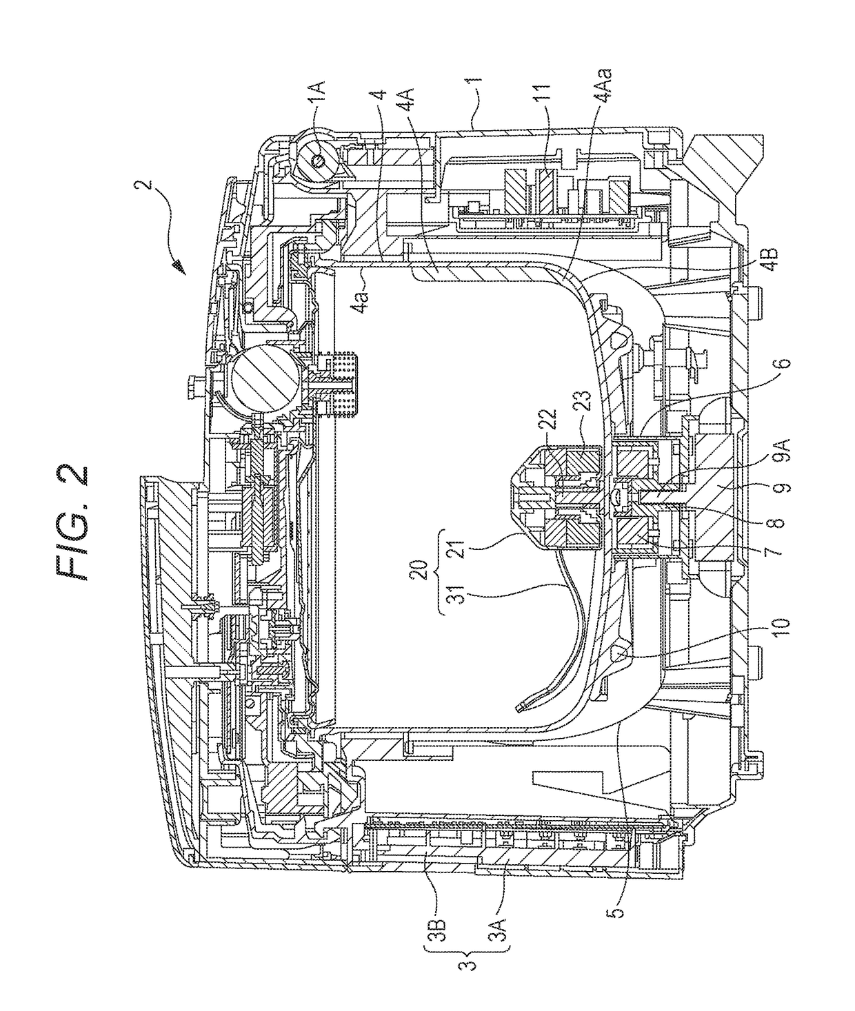
[0051]A heating cooker according to the first exemplary embodiment of the present invention is a heating cooker having a stirring function that includes a stirring body configured to stir cooking materials housed in a cooking container. FIG. 1 is a perspective view of the heating cooker according to the present exemplary embodiment. FIG. 2 is a sectional view of the heating cooker according to the present exemplary embodiment.

[0052]As shown in FIG. 1, the heating cooker of the present exemplary embodiment includes apparatus body 1 having a substantially bottomed cylindrical shape, and lid 2 that openably covers an upper opening of apparatus body 1. As shown in FIG. 2, lid 2 is rotatably mounted to hinge part 1A provided at an upper rear part (upper right in FIG. 2) of apparatus body 1.

[0053]Apparatus body 1 has, at its front, operation unit 3 provided for various operations including selection of a cooking menu. Operation unit 3 includes operation key group 3A and display 3B. Operat...

second exemplary embodiment

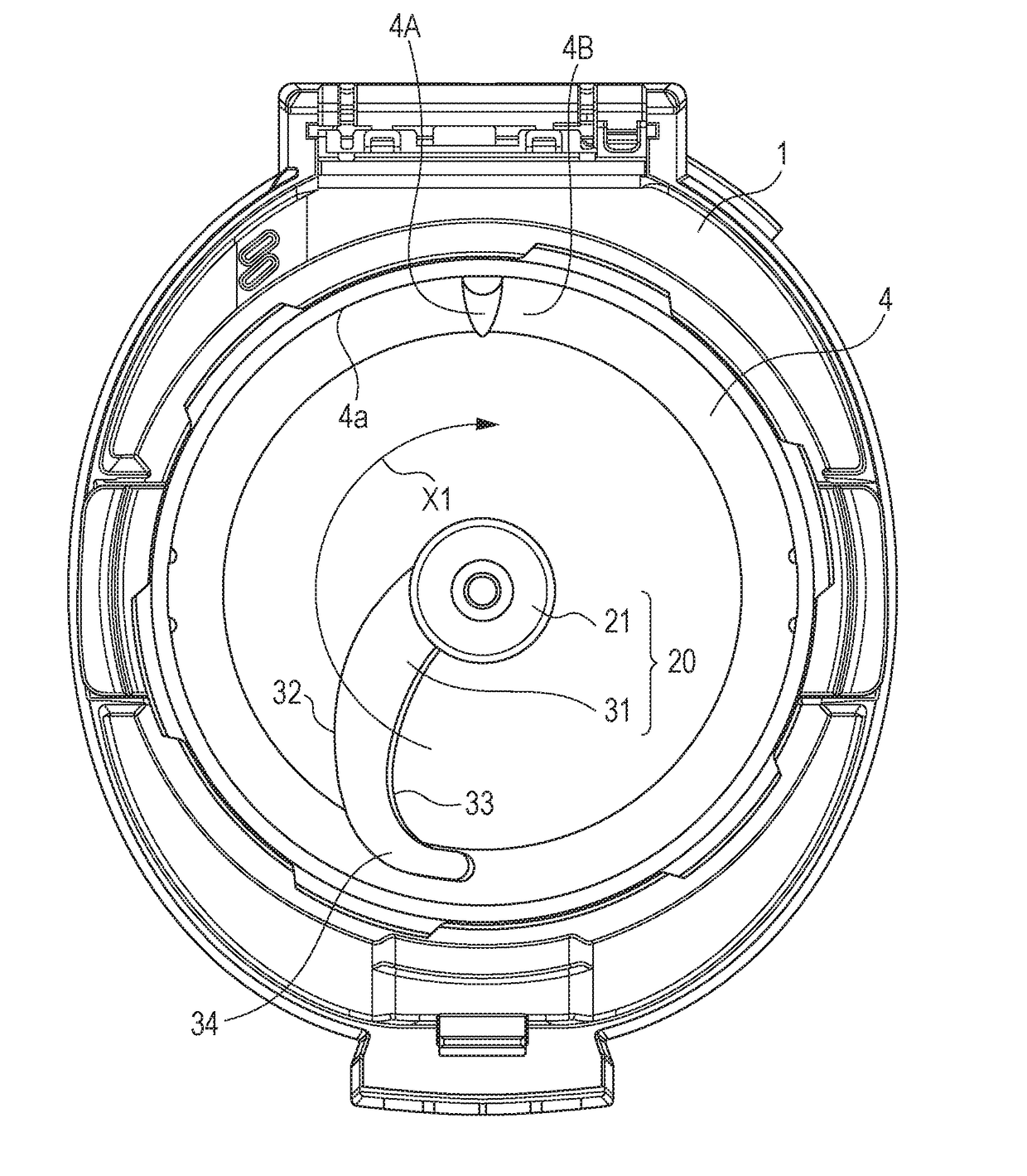
[0096]FIG. 12 is a sectional view of a heating cooker according to the second exemplary embodiment of the present invention. FIG. 13 is a plan view illustrating the heating cooker of FIG. 12 with a lid removed therefrom. FIG. 14 is a perspective view of a stirring body of the heating cooker of FIG. 12. The heating cooker of the second exemplary embodiment differs from the heating cooker of the first exemplary embodiment in that leading end portion 34 of blade 31 is provided with vertical wall 35 standing upward from front edge 32 along inner peripheral surface 4a of cooking container 4.

[0097]Vertical wall 35 functions to inhibit cooking materials that ride on third stirring region E3 along with rotation of blade 31 from falling toward and adhering to inner peripheral surface 4a of cooking container 4. In the present exemplary embodiment, a section corresponding to vertical wall 35 is referred to as “fourth stirring region E4” as shown in FIG. 14.

[0098]According to the heating cooker...


PUM


Abstract

A stirring body of the present invention includes housing rotatably mounted to a center of a bottom surface of a cooking container, and blade that extends from an outer peripheral surface of housing toward an inner peripheral surface of the cooking container and curves convexly toward a downstream side of a rotating direction in a plan view. Blade has front edge positioned on the downstream side in the rotating direction, and rear edge positioned on an upstream side in the rotating direction relative to front edge. A leading end portion of blade curves along the inner peripheral surface of the cooking container in the plan view and slopes upward toward the upstream side in the rotating direction. Front edge is positioned below rear edge near housing and is positioned above rear edge near leading end portion.

Description

TECHNICAL FIELD[0001]The present invention relates to a heating cooker having a stirring function that includes a stirring body configured to stir cooking materials in a cooking container.BACKGROUND ART[0002]Conventional heating cookers of this type are described with reference to FIGS. 15 to 17.[0003]FIG. 15 is a perspective view of a stirring body of one of the conventional heating cookers. As shown in FIG. 15, stirring body 100 includes pushing part 101 that pushes cooking materials toward an inner peripheral surface of a cooking container, and turnover part 102 that turns over the cooking materials positioned near the inner peripheral surface of the cooking container toward a center of the cooking container while stirring body 100 rotates on rotation axis 100A inside the cooking container. Pushing part 101 is formed to curve convexly toward a downstream side in rotating direction X100 in a plan view and to reduce in height toward turnover part 102. Turnover part 102 has first sl...

Claims


Application Information

Patent Timeline
IPC IPC(8): A47J27/00A47J36/16
CPCA47J36/165A47J27/00A47J43/0722A47J27/004A47J43/046
Inventor OHTA, KATSUYUKINISHIMURA, MAKOTO
Owner PANASONIC INTELLECTUAL PROPERTY MANAGEMENT CO LTD
Learn More