
Tool assembly for leak resistant tissue dissection

a technology for tissue dissection and tool assembly, which is applied in the field of tool assembly for leak-resistant tissue dissection, can solve the problems of difficult for a clinician to maintain a straight cut line, the tool assembly of the surgical stapling device may not be long enough to cut across the entire length of the body organ, and the termination point is susceptible to leakag

Inactive Publication Date: 2017-12-21
TYCO HEALTHCARE GRP LP
View PDF31 Cites 598 Cited by
  • Summary
  • Abstract
  • Description
  • Claims
  • Application Information

AI Technical Summary

Benefits of technology

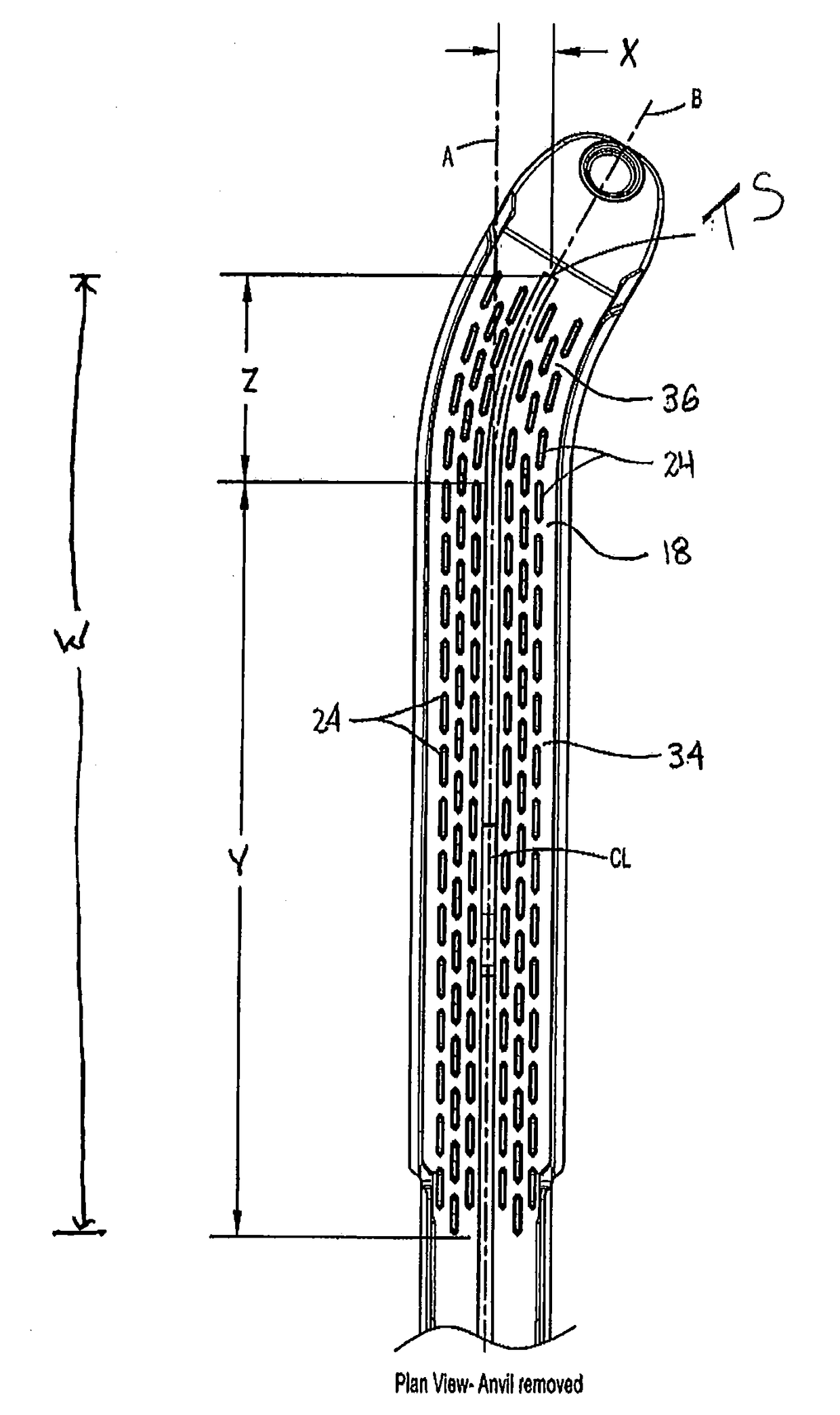
The present disclosure describes a tool assembly for tissue dissection that includes a cartridge assembly and an anvil. The cartridge has a longitudinal portion and a transverse portion with staple receiving pockets and a knife slot. The anvil has a longitudinal portion and a transverse portion with staple deforming depressions. The cartridge and anvil have curvilinear portions that define a radius of curvature. The tool assembly has a length of at least 6 cm to prevent leakage. It is designed for leak resistant tissue dissection. The technical effects of the tool assembly are improved leak resistance, precise tissue dissection, and efficient tissue dissection with reduced bleeding and complications.

Problems solved by technology

In some procedures, e.g., gastrectomy procedures, a tool assembly of the surgical stapling device may not be long enough to cut across the entire length of the body organ.
Since known surgical staplers do not apply a staple across the vertex of the termination point, the termination point is susceptible to leakage.
Where multiple cutting operations are required, it can be difficult for a clinician to maintain a straight cut line while properly sealing the termination points of the cut line.

Method used


Image

  • Tool assembly for leak resistant tissue dissection
  • Tool assembly for leak resistant tissue dissection
  • Tool assembly for leak resistant tissue dissection

Examples


Embodiment Construction

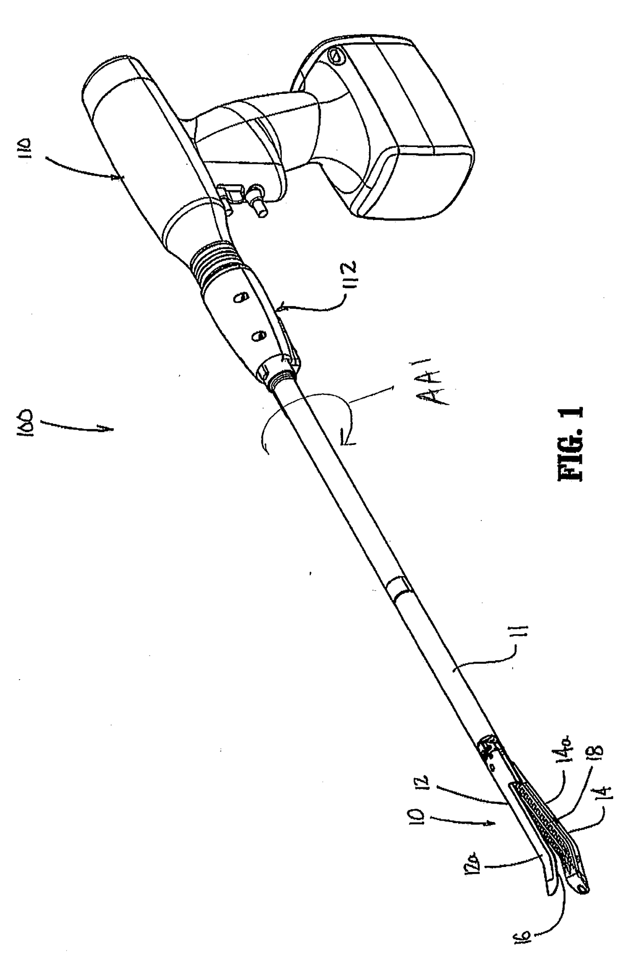
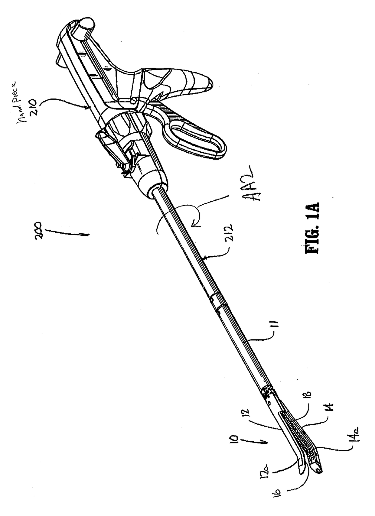
[0028]The presently disclosed tool assembly for leak resistant dissection of tissue will now be described in detail, as part of a surgical stapling device, with reference to the drawings in which like reference numerals designate identical or corresponding elements in each of the several views. In this description, the term “clinician” is used generally to refer to medical personnel including doctors, nurses, and support personnel, the term “proximal” is used generally to refer to the portion of the device that is closer to a clinician, and the term “distal” is used generally to refer to the portion of the device that is farther from the clinician. In addition, the term “endoscopic” is used generally to refer to endoscopic, laparoscopic, arthroscopic, and any other surgical procedure performed through a small incision or a cannula inserted into a patient's body. Finally, the term “specimen side” is used generally to refer to the side or portion of body tissue that is being removed f...


PUM


Abstract

A tool assembly for leak resistant dissection of tissue includes an anvil and a cartridge housing a plurality of staples. The anvil and cartridge have a linear longitudinal portion and a transverse portion positioned distally of the longitudinal portion. The linear longitudinal portion of the cartridge and anvil assemblies is substantially longer than the curved distal portion. In use, when a surgical procedure is performed that requires a plurality of cutting operations, e.g., a gastrectomy procedure, the first cutting operation is performed to form a substantially linear cut line having a curved distal portion that curves towards a specimen side of the organ, e.g., the stomach. In each subsequent cutting operation, the proximal portion of the tool assembly is positioned with the existing cut line such that a termination point of the existing cut line is positioned on the specimen side of the tissue or organ being partially removed.

Description

BACKGROUND1. Technical Description[0001]The present disclosure is directed to linear surgical stapling devices, and more particularly, to linear surgical stapling devices that include a tool assembly having a longitudinal proximal portion and a curved and / or angled distal portion to facilitate leak resistant dissection of body tissue.2. Background of Related Art[0002]The use of linear surgical stapling devices to perform total or partial removal of a body organ from a patient is known. In some procedures, e.g., gastrectomy procedures, a tool assembly of the surgical stapling device may not be long enough to cut across the entire length of the body organ. In these situations, it is necessary to perform a plurality of cutting operations with the surgical stapling device to remove the organ or a portion of the organ from the patient.[0003]During each cutting operation of a surgical stapling device, tissue is divided along a cut line and staples are applied along the cut line to seal th...

Claims


Application Information

Patent Timeline
IPC IPC(8): A61B17/10A61B17/32A61B17/068
CPCA61B17/105A61B17/32A61B17/068A61B17/07207A61B2017/00398A61B2017/07221
Inventor SGROI, ANTHONY
Owner TYCO HEALTHCARE GRP LP
Learn More