Profiled rail system for covering the end of a flooring

Inactive Publication Date: 2017-12-21
SONDERMANN FR
View PDF4 Cites 5 Cited by
  • Summary
  • Abstract
  • Description
  • Claims
  • Application Information

AI Technical Summary

Benefits of technology

[0009]Further alternatively or additionally the at least one elastic body is at least partially provided above a foot being provided on the at least one mounting profiled rail. By this way the at least one elastic body pushes the at least one mounting profiled rail against the base profiled rail and hereby provides the required prestress of the at least one covering wing against the flooring. By this way at least part of the height adjustability of the profiled rail system can be realised. In simple applications this type of height adjustability can be sufficient. Alternatively an additional height adjustability can be realised by allowing movability in the connection between the at least one covering profiled rail and the at least one mounting profiled rail.
[0010]In a further advantageous embodiment of the present invention the at least one elastic body is formed in a way that the at least one mounting profiled rail being completely separated from the at least one base profiled rail. By this way it is ensured that any conjunction between the at least one mounting profiled rail and the at least one base profiled rail is realised by the at least one elastic body only. By this way oscillations transferred across this conjunction are damped, hereby realising an additional step and/or room noise damping. Additionally the profiled rails are hereby protected against abrasion due to loads.
[0011]For the at least one elastic body use of at least one polymer foam is preferred. This polymer foam can be easily produced and it is cheap due to the small amount of material being necessary. Additionally polymer foam has the advantage that is comprises structural inhomogeneity and hereby providing an enhanced noise damping. In the case,

Problems solved by technology

Such seizing often occurs, if the covering profiled rail is mounted on the mounting profiled rail with extremely high force.
This can cause inhibition of the movement of the flooring below the at least one covering wing.
This v

Method used


Image

  • Profiled rail system for covering the end of a flooring
  • Profiled rail system for covering the end of a flooring
  • Profiled rail system for covering the end of a flooring

Examples


Embodiment Construction

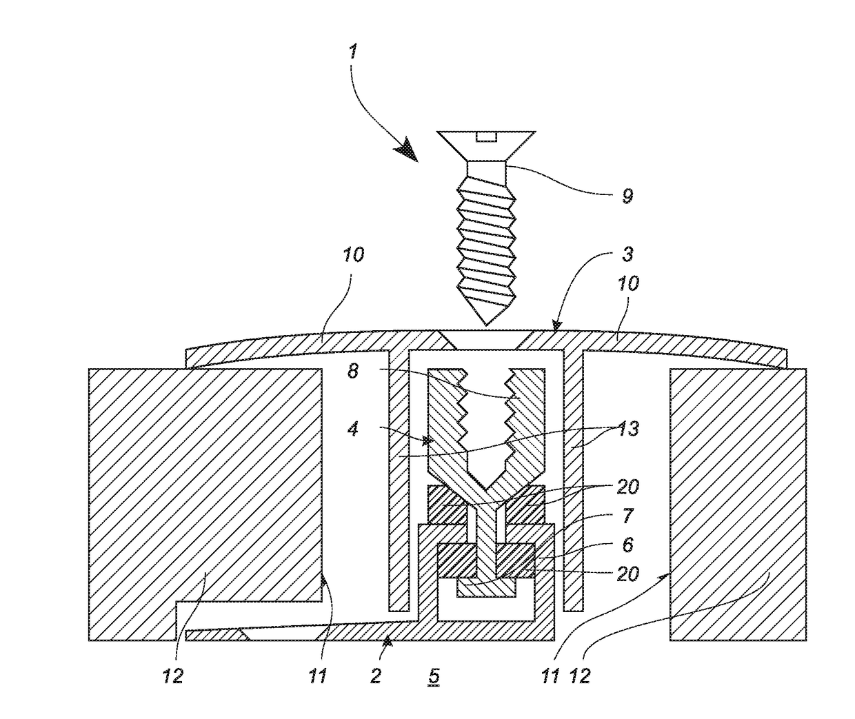
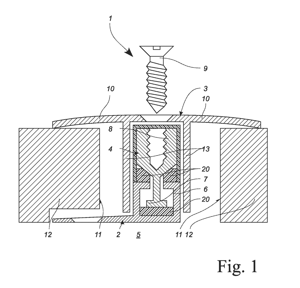
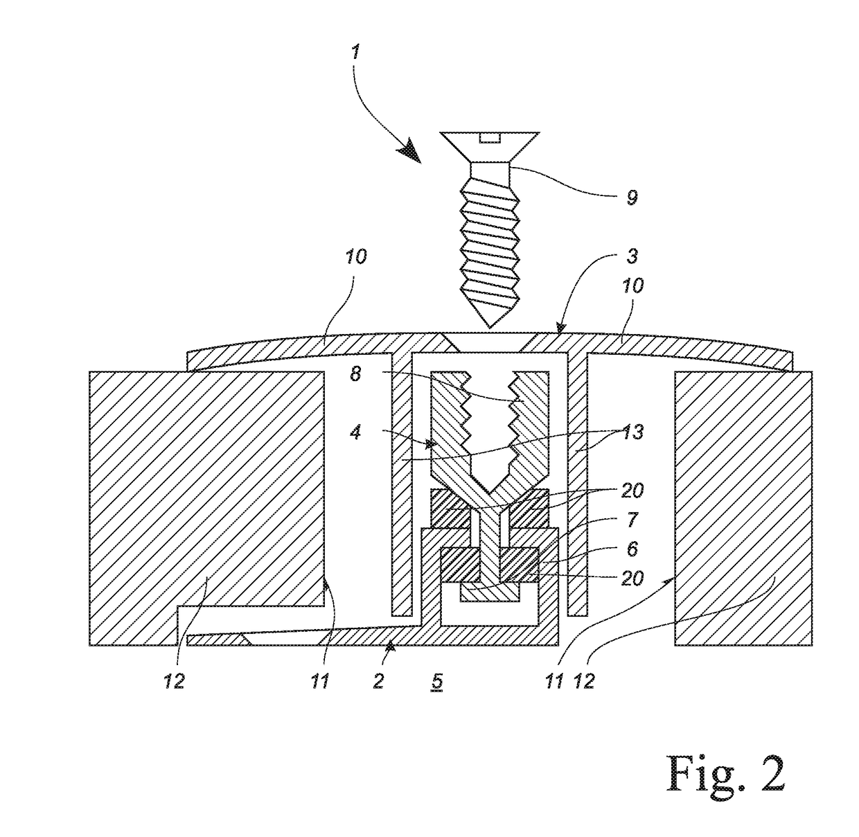
[0020]FIG. 1 shows a cross section of a profiled rail system 1, comprising a base profiled rail 2, a covering profiled rail 3 and a mounting profiled rail 4. The base profiled rail 2 is mounted by means of non shown mounting means, in particular screws with an underground 5. The base profiled rail 2 comprises mounting means 6, being realised by means of vertically extending webs, being deviated to the interior at the top end. Between holding means 6 a foot 7 of the mounting profiled rail 4 is provided. This foot 7 is made sufficiently broad, to realise a top abutment for the holding means 6 of the mounting profiled rail 4, in order to safely hold the mounting profiled rail 4 on the base profiled rail 2.

[0021]The mounting profiled rail 4 provides a mounting channel 8 for receiving further holding means 9 in form of a screw. These holding means 9 connect the covering profiled rail 3 with the mounting profiled rail 4. By means of more or less deep turning of the holding means 9 a certa...


PUM


Abstract

A profiled rail system (1) for covering at least one flooring end (11) comprises a base profiled rail (2) and a covering profiled rail (3), being connectable with each other by means of a mounting profiled rail (4). The covering profiled rail (3) comprising at least one covering wing (10) for overlapping the flooring end (11). The covering profiled rail (3) is mountable on the mounting profiled rail (4). The base profiled rail (2) comprises holding means for connecting the mounting profiled rail (4). Between the base profiled rail (2) and the mounting profiled rail (4) at least one elastic body (20) is provided, holding the mounting profiled rail (4) in an unloaded situation in a predefined position. The mounting profiled rail (4) can be pivoted relatively to the base profiled rail (2) by means of elastically deformation of the elastic body (20).

Description

CROSS-REFERENCE TO RELATED APPLICATION[0001]The present application claims priority to German Utility Model Application no:[0002]DE 20 2016 003 728.6, filed Jun. 15, 2016, which is incorporated herein by reference in its entirety.FIELD OF THE INVENTION[0003]The present invention relates to a profiled rail system for covering at least one end of a flooring, the profiled rail system comprising at least one base profile at it least one covering profile.BACKGROUND OF THE INVENTION[0004]From the state of the art profiled rail systems are known comprising three profiled rails, namely a base profiled rail for fastening to the underground, covering profiled rail comprising a covering wing, overlapping the end of the flooring and a mounting profiled rail for connecting both together. The covering profiled rail is connected to the mounting profiled rail. To achieve an adjustability for the covering profiled rail, namely for pivoting the same, the mounting profiled rail is moveable with respec...

Claims


Application Information

Patent Timeline
IPC IPC(8): E04B1/68E04B5/02E04F15/02
CPCE04B1/6804E04B1/6803E04B5/023E04F15/02005E04F19/02E04F19/062E04F19/066E04F19/068
Inventor SONDERMANN, FRANK
Owner SONDERMANN FR
Why Eureka
Try Eureka