
Shovel

Active Publication Date: 2018-01-04
SUMITOMO CONSTRUCTION MACHINERY
View PDF23 Cites 2 Cited by
  • Summary
  • Abstract
  • Description
  • Claims
  • Application Information

AI Technical Summary

Benefits of technology

The technical effect of this patent is that the shovel can quickly determine if there is an operation to be performed on its components, and then control the engine's revolution speed accordingly. This helps to rapidly and efficiently control the shovel's performance.

Problems solved by technology

However, the engine revolution speed does not instantaneously increase, and a certain time duration is required for the engine revolution speed to reaches a revolution speed necessary for driving.
Therefore, there may be a drawback that the shovel is not operated to perform an ordinary speed and power until the engine revolution speed becomes the ordinary revolution speed for the running operation.

Method used


Image

  • Shovel
  • Shovel
  • Shovel

Examples


Embodiment Construction

[0017]Embodiments of the present invention are described with reference to figures.

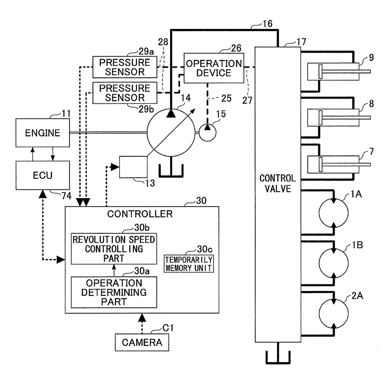
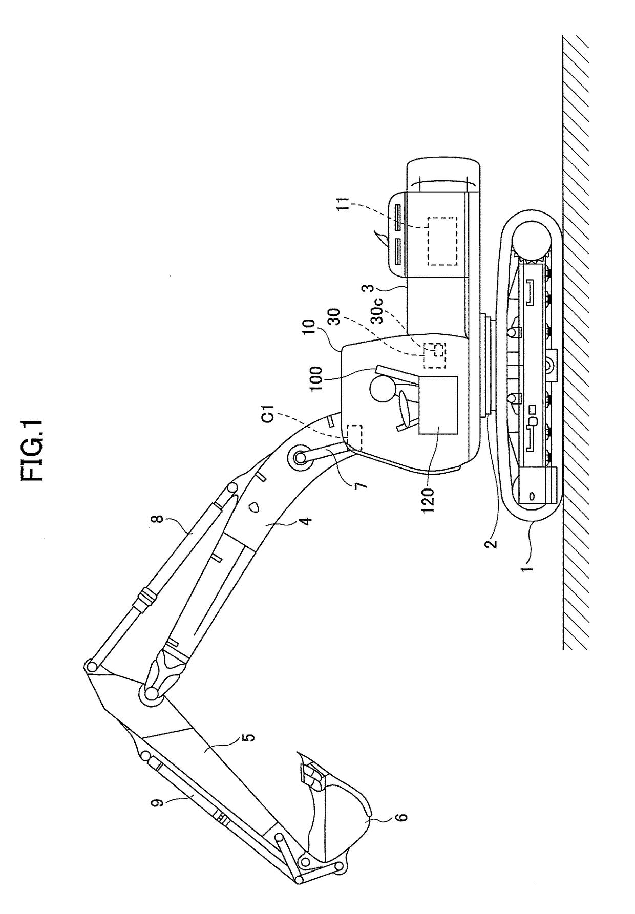
[0018]FIG. 1 is a side view of the shovel of the embodiment. In the shovel, an upper-part swiveling body 3 is installed in a lower-part traveling body 1 through a swivel mechanism 2 so as to be rotatable relative to the lower-part traveling body 1. A boom 4 is attached to the upper-part swiveling body 3. An arm 5 is attached to a tip end of the boom 4. A bucket 6 as an end attachment is attached to the tip end of the arm 5.

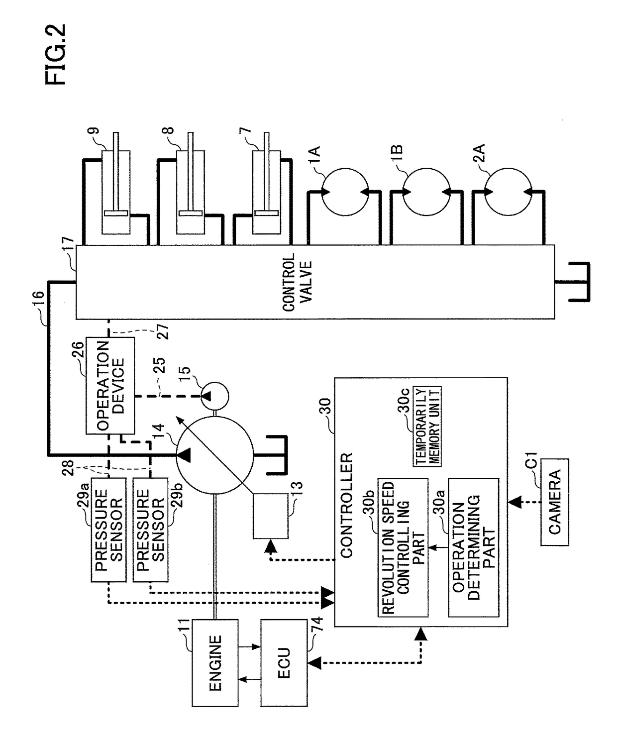
[0019]The boom 4, the arm 5, and the bucket 6 form a drilling attachment as an example of the attachment. The boom 4, the arm 5, and the bucket 6 are hydraulically driven by a boom cylinder 7, an arm cylinder 8, and a bucket cylinder 9, respectively.

[0020]A cabin 10 as a driver's cabin is installed in the upper-part swiveling body 3. An engine 11 as a power source of the shovel is installed on a back side of the cabin 10 of the upper-part swiveling body 3. The engine 11 is an intern...


PUM


Abstract

A shovel enabled to set an engine revolution speed to revolution speeds including a revolution speed for a running operation and a revolution speed for an idling running operation that is lower than the revolution speed for the running operation includes an engine provided as a driving source of the shovel, an operating part configured to be driven by a driving force of the engine, an operation component configured to operate the operating part, a detecting device configured to detect a position of a movable portion of an operator and a position of the operation component, an operation determining part configured to determine a positional relationship between the movable portion and the operation component, and a control part configured to set the engine revolution speed of the engine based on the positional relationship between the movable portion and the operation component that is determined by the operation determining part.

Description

CROSS-REFERENCE TO RELATED APPLICATIONS[0001]This application is a continuation application filed under 35 U.S.C. 111(a) claiming the benefit under 35 U.S.C. 120 and 365(c) of a PCT International Application No. PCT / JP2016 / 058437 filed on Mar. 17, 2016, which is based upon and claims the benefit of priority of the prior Japanese Patent Application No. 2015-058709 filed on Mar. 20, 2015, the entire contents of which are incorporated herein by reference.BACKGROUND OF THE INVENTION1. Field of the Invention[0002]The present invention generally relates to a shovel, in which a target set revolution speed of an engine can be changed.2. Description of the Related Art[0003]There is a shovel having an auto idling function, by which the revolution speed of an engine is automatically decreased (switching to an idling running operation) when a no-operation state continues in the construction machine.[0004]Switching to the idling running operation in the auto idling function is determined whether...

Claims


Application Information

Patent Timeline
IPC IPC(8): E02F9/20E02F3/32F02D31/00
CPCE02F9/2066E02F9/2004F02D31/001E02F3/32F02D29/04F02D11/02F02D2200/602F02D2200/604F02D41/021F02D41/08E02F9/2246E02F9/2235E02F3/435F02D41/16F02D29/02F02D2200/101F02D29/00E02F9/20F02D45/00
Inventor MISAKI, YOUJI
Owner SUMITOMO CONSTRUCTION MACHINERY
Learn More