Ice making for making single layer and double layer ice brick

Inactive Publication Date: 2018-01-18
HSU HSU HUI
View PDF0 Cites 5 Cited by
  • Summary
  • Abstract
  • Description
  • Claims
  • Application Information

AI Technical Summary

Benefits of technology

[0005]According to improve the defect in the prior art, the present invention provides an ice making machine, in that in the structure of the present invention, by the round receiving groove of the isolating plate which receives the condensing basin, the condensing basin will not move horizontally. By the limiting groove with a plurality of limiting rods which is engaged with the two ears, it is avoided that the condensing basin rotates unwill

Problems solved by technology

Furthermore, the prior art ice making machine only makes

Method used


Image

  • Ice making for making single layer and double layer ice brick
  • Ice making for making single layer and double layer ice brick
  • Ice making for making single layer and double layer ice brick

Examples


Example

[0022]In order that those skilled in the art can further understand the present invention, a description will be provided in the following in details.

[0023]However, these descriptions and the appended drawings are only used to cause those skilled in the art to understand the objects, features, and characteristics of the present invention, but not to be used to confine the scope and spirit of the present invention defined in the appended claims.

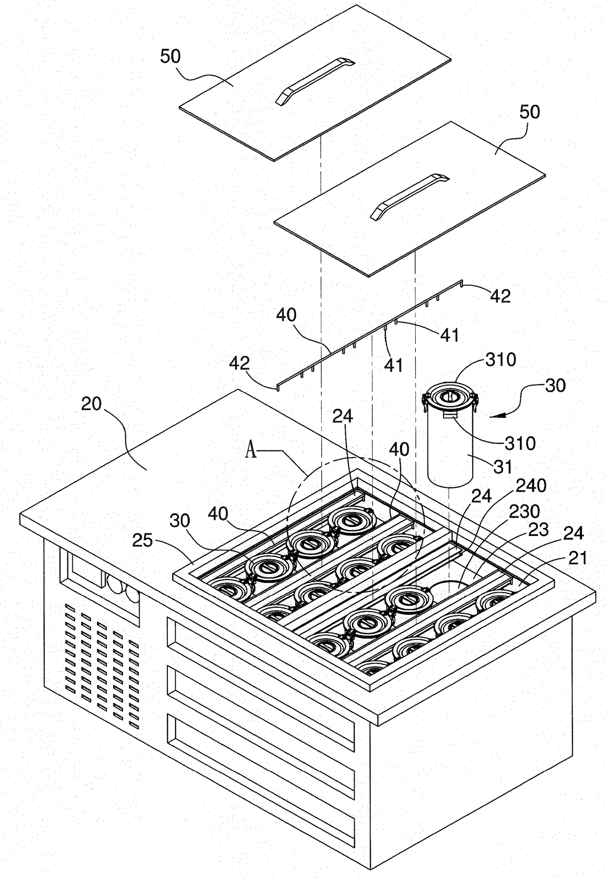
[0024]With reference to FIGS. 4 to 6, the ice making machine of the present invention is illustrated. The present invention includes the following elements.

[0025]A machine table 20 has a condensing tank 21 with an upward opening for receiving condensing liquid. A plurality of condensing tubes 22 are installed within the bottom of the condensing tank 21. An isolating plate 23 and a plurality of limiting rods 24 are installed in the condensing tank 21 within the opening. A plurality of receiving grooves 230 are formed on the isolating plate 23, ...


PUM


Abstract

An ice making machine has round receiving groove in the isolating plate for receiving the condensing basin, the condensing basin will not move horizontally. By the limiting groove with a plurality of limiting rods which is engaged with the two ears, it is avoided that the condensing basin rotates unwillingly. Especially, a single layer ice brick can be made by using the inner basin with the outer basin. Or the use of the core basin with the outer basin, an inner layer ice brick c is made firstly. Then the use of the inner basin with the outer basin cause an inner ice brick d is made. Therefore, a double layer ice brick is formed with two odors or two colors. By use of the inner basin and the outer tube, the ice brick can be easily taken out.

Description

FIELD OF THE INVENTION[0001]The present invention relates to ice making machine for forming ice bricks; and in particular to an ice making machine for making single layer and double layer ice brick.BACKGROUND OF THE INVENTION[0002]FIGS. 1 to 3, a prior art ice making machine is illustrated. The ice making machine includes a machine table 10, a plurality of condensing tanks 11 and a plurality of cover plates 12. The machine table 10 has an upward opening and a rectangular condensing groove 100 for receiving condensing liquid. A bottom of the condensing groove 100 has a plurality of condensing tubes 101 near a bottom thereof. Near an opening of the condensing groove 100 has an isolating plate 102 which has a plurality of round receiving holes 103. A cover frame 104 is installed at the opening of the condensing groove 100. The plurality of condensing tanks 11 can be received into the receiving holes 103. Each condensing tank 11 has a tank body 110 and a cover 111. The tank body 110 has...

Claims


Application Information

Patent Timeline
IPC IPC(8): F25C1/04F25C1/22F25C1/18F25D3/04
CPCF25C1/04F25C1/22F25C1/18F25D2303/0845F25C2400/06F25D2303/0843F25D3/04
Inventor HSU, HSU- HUI
Owner HSU HSU HUI
Why Eureka
Try Eureka