Screen printed phosphors for intrinsic chip identifiers

a chip identification and phosphor technology, applied in the field of physical unclonable functions, can solve the problems of difficult to ensure that the measurement of a given puf will be consistent, and existing attempts at creating pufs suffer from a lack of reproducibility in measurement, so as to achieve substantial spatial variability

Active Publication Date: 2018-01-18
IBM CORP
View PDF52 Cites 4 Cited by
  • Summary
  • Abstract
  • Description
  • Claims
  • Application Information

AI Technical Summary

Benefits of technology

[0004]A method for generating an identifier includes detecting emissions from a phosphor pattern with a sensor grid comprising one or more sensors when the phosphor pattern is stimulated with radiation. An output signal of each sensor in the sensor grid is compared to a threshold value to generate respective identifier bits. An identifier is generated from the identifier bits.
[0005]A method for generating an identifier includes illuminating a phosphor pattern that has substantial spatial variability in a density of phosphor material with soft x-rays having a wavelength between about 2 nm and about 20 nm. Emissions from the phosphor pattern are detected with a sensor grid directly above the phosphor pattern at a distance of about 1 μm. The sensor grid includes one or more sensors. An output signal of each sensor in the sensor grid is compared to a threshold value to generate respective identifier bits, assigning a logical ‘1’ if the output signal of a sensor is above the threshold value and assigning a logical ‘0’ if the output signal of a sensor is below the threshold value. An identifier is generated from the identifier bits. A color sensitivity of the sensor grid is changed. The illuminating, detecting, comparing, and generating steps are repeated to generate a second identifier.
[0006]A system for generating an identifier includes phosphor pattern that emits radiation when illuminated. A sensor grid has one or more sensors, with each sensor being configured to detect the radiation from the phosphor pattern. An identifier module is configured to compare an output signal of each sensor in the sensor grid to a threshold value, to generate respective identifier bits based on said comparison, and to generate an identifier from the identifier bits.

Problems solved by technology

Existing attempts at creating PUFs suffer from a lack of reproducibility in measurement.
In particular, it is difficult to ensure that the measurement of a given PUF will be consistent from one measurement to the next.

Method used


Image

  • Screen printed phosphors for intrinsic chip identifiers
  • Screen printed phosphors for intrinsic chip identifiers
  • Screen printed phosphors for intrinsic chip identifiers

Examples


Embodiment Construction

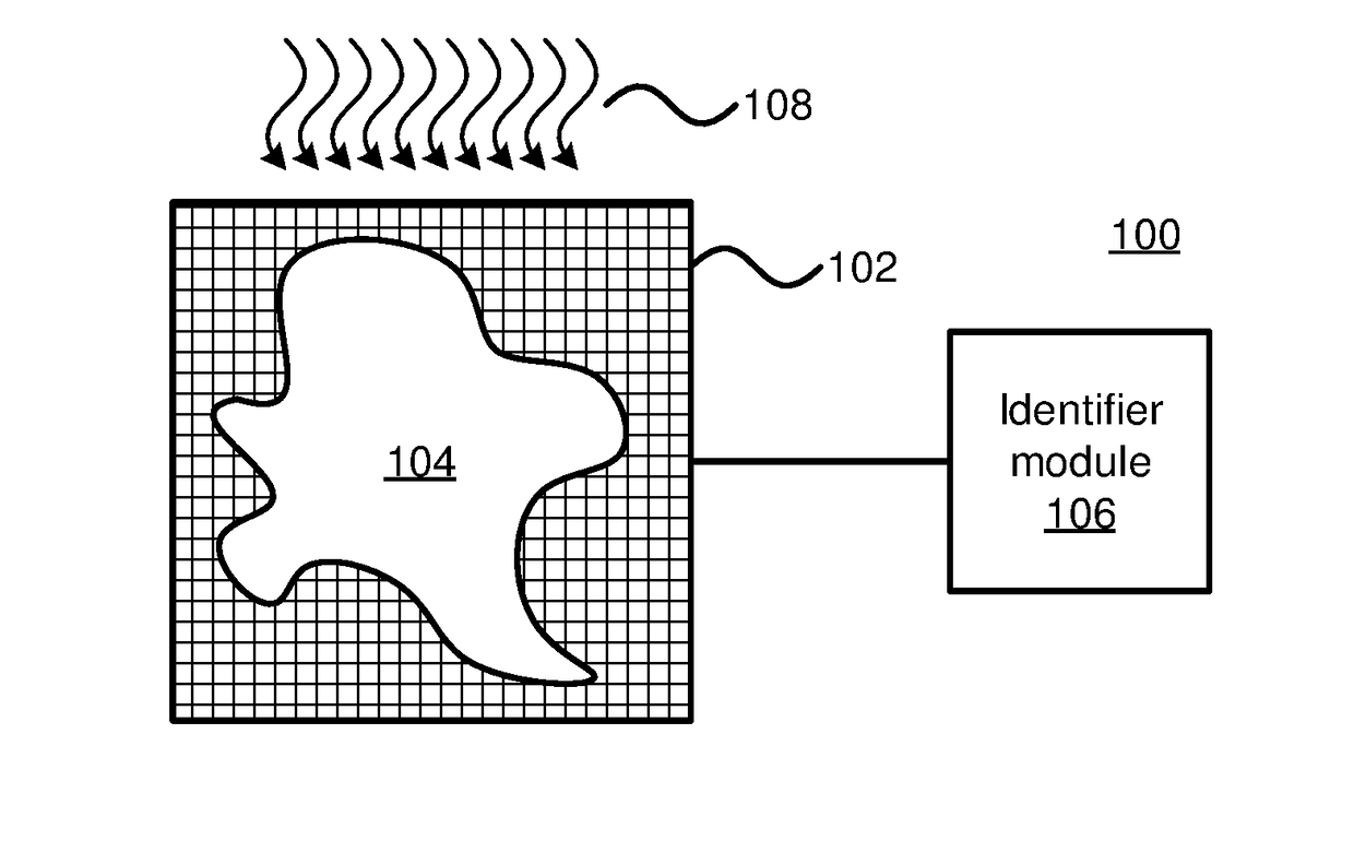
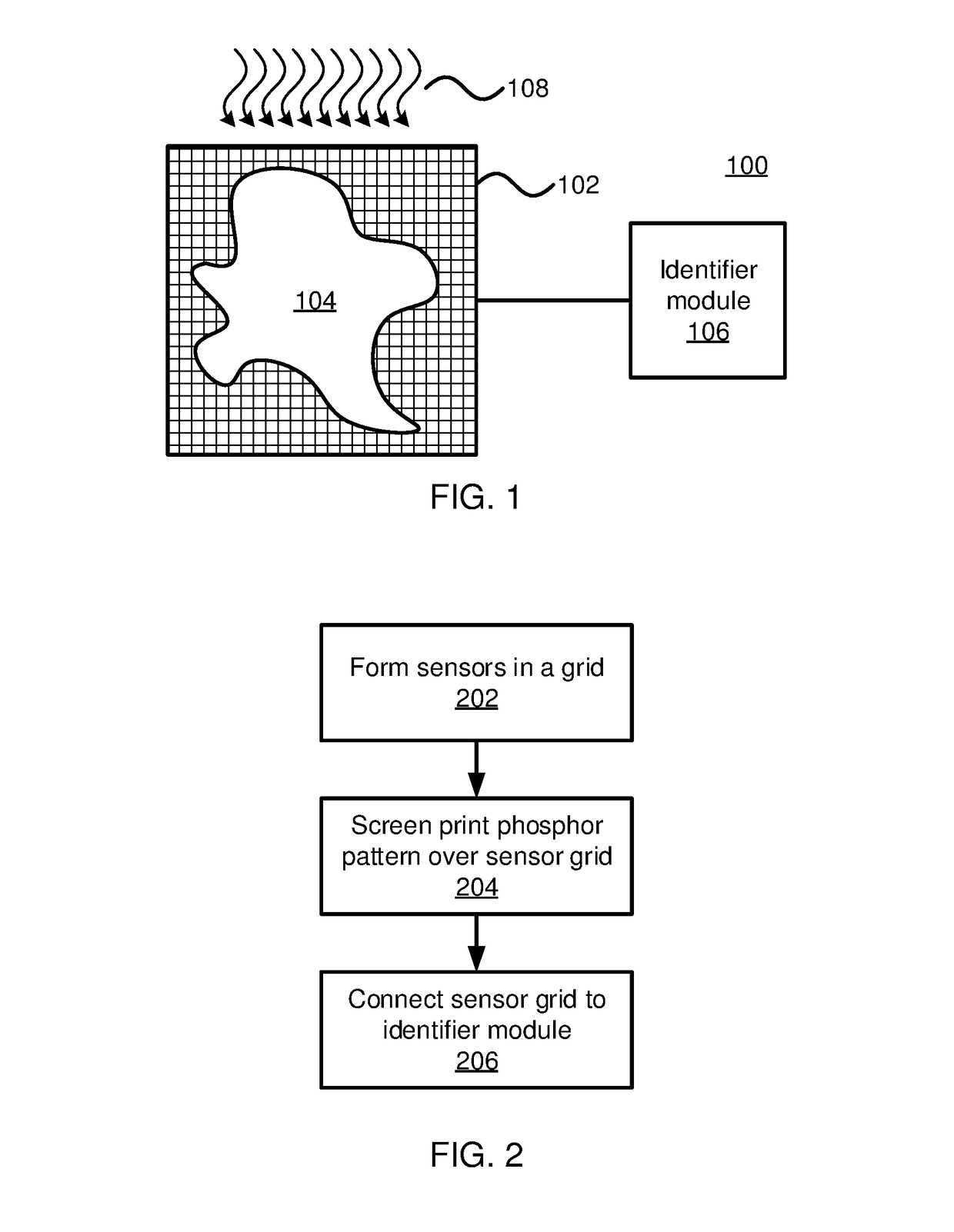
[0017]Embodiments of the present invention provide physically unclonable functions (PUFs) in the form of screen-printed phosphor patterns. The screen-printing process, specifically when applied to phosphor particles embedded in a matrix, creates a significant amount of variability, such that the printed pattern will differ measurably from device to device. The pattern can be applied to an on-chip imaging sensor and activated by emissions through a device housing.

[0018]Referring now to FIG. 1, an exemplary PUF system 100 is shown. In particular, a screen-printed phosphor pattern 104 is applied over an imaging sensor grid 102. The imaging sensor grid 102 may be implemented with any appropriate sensor technology to form a grid that is, e.g., 100 pixels by 100 pixels. The sensor grid 102 may have a size that is selected in accordance with security needs, where a larger grid will provide additional identifier bits. In one specific embodiment, it is contemplated that the sensor grid 102 m...


PUM

PropertyMeasurementUnit
wavelengthaaaaaaaaaa
distanceaaaaaaaaaa

Abstract

Methods and systems for generating an identifier include detecting emissions from a phosphor pattern with a sensor grid comprising one or more sensors when the phosphor pattern is stimulated with radiation. An output signal of each sensor in the sensor grid is compared to a threshold value to generate respective identifier bits. An identifier is generated from the identifier bits.

Description

BACKGROUNDTechnical Field[0001]The present invention generally relates to physically unclonable functions and, more particularly, to the use of variability in the screen-printing of phosphors to create a physically unclonable function.Description of the Related Art[0002]Physically unclonable functions (PUFs) are used to uniquely identify a piece of hardware by providing a unique identifying signal that is difficult to counterfeit. PUFs have the following basic properties: 1. They cannot be easily copied; 2. They are read out in a non-obvious manner (e.g., no optical readout); 3. They are unique; and 4. They generate a highly reproducible output, even with a fuzzy readout.[0003]Existing attempts at creating PUFs suffer from a lack of reproducibility in measurement. In particular, it is difficult to ensure that the measurement of a given PUF will be consistent from one measurement to the next.SUMMARY[0004]A method for generating an identifier includes detecting emissions from a phosph...

Claims


Application Information

Patent Timeline
Patent Type & Authority Applications(United States)
IPC IPC(8): G01N23/223
CPCG01N2223/611G01N23/223G06F21/73H04L9/3278G06F21/60G06F21/70G06F21/71H04L9/3271
Inventor PFEIFFER, DIRKROSENBLATT, SAMIKOTHANDARAMAN, CHANDRASEKARA
Owner IBM CORP
Why Eureka
Try Eureka