Battery monitoring system

Active Publication Date: 2018-01-25
YAZAKI CORP
View PDF4 Cites 17 Cited by
  • Summary
  • Abstract
  • Description
  • Claims
  • Application Information

AI Technical Summary

Benefits of technology

The patent text describes a new battery monitoring system that improves the reliability and safety of the whole system by detecting any failure in the voltage detection device used in the system. The system can continue to function properly even if there is a failure in one of the measuring routes. This improves the reliability of the battery monitoring system and ensures the safety of the whole system.

Problems solved by technology

With charge to and discharge from respective battery cells performed repeatedly, the battery pack gradually deteriorates over time and additionally, the output voltage of each battery cell changes.
Therefore, the conventional voltage detection device has a problem that the reliability in detecting a failure is low.
Additionally, for a situation where both of two measuring routes output the same measurement result and are out of order, it is expected that a power supply or the like used in both measuring routes in common may have a failure.
Nevertheless, as the voltage detection device of the conventional example cannot detect such a failure, it is unlikely that one can take a measure of suspending the use of a battery pack as an object to be monitored and stopping an apparatus such as a vehicle mounting the battery pack, thereby raising a problem of inferior function safety of the whole system.

Method used


Image

  • Battery monitoring system
  • Battery monitoring system
  • Battery monitoring system

Examples


Embodiment Construction

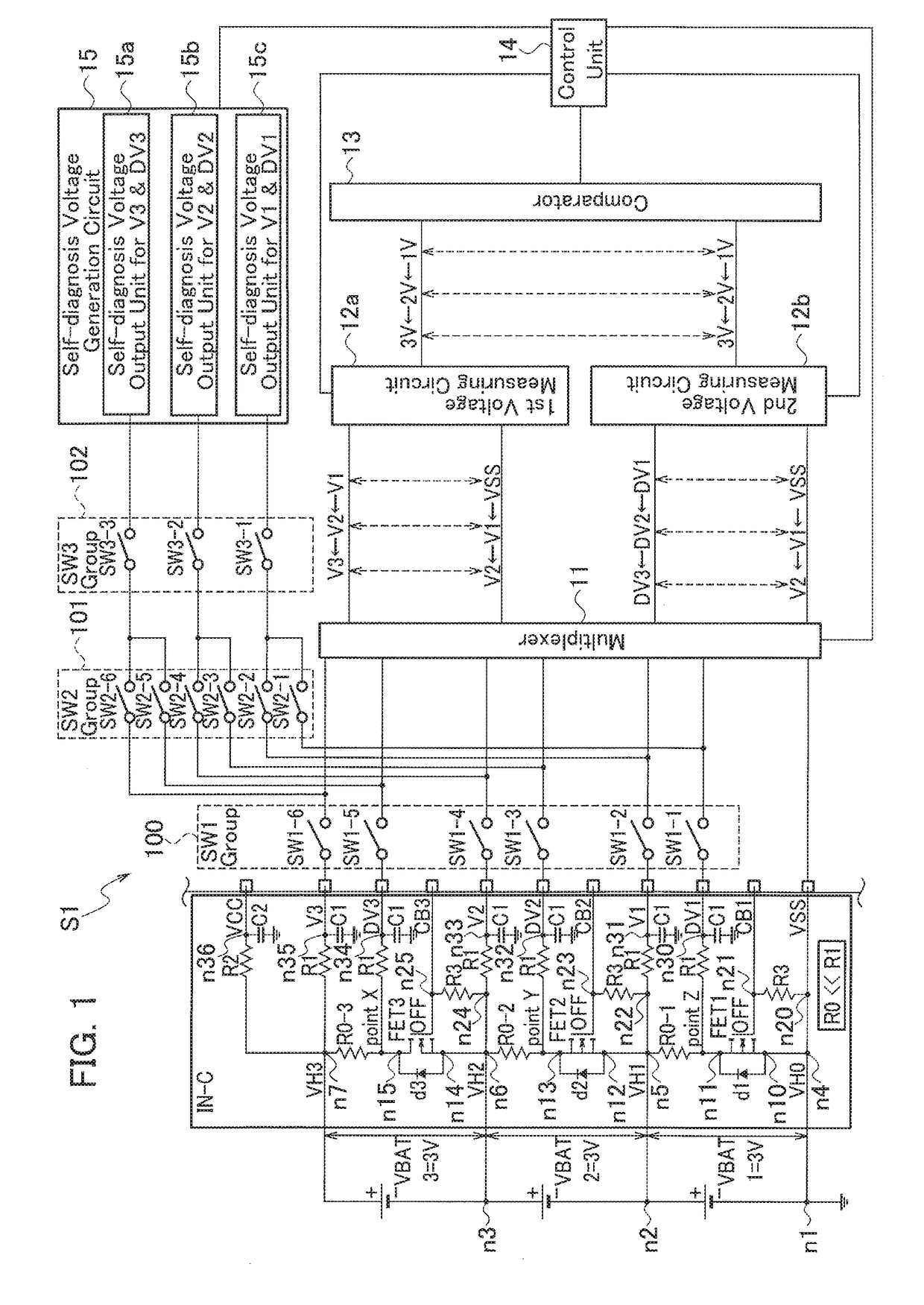
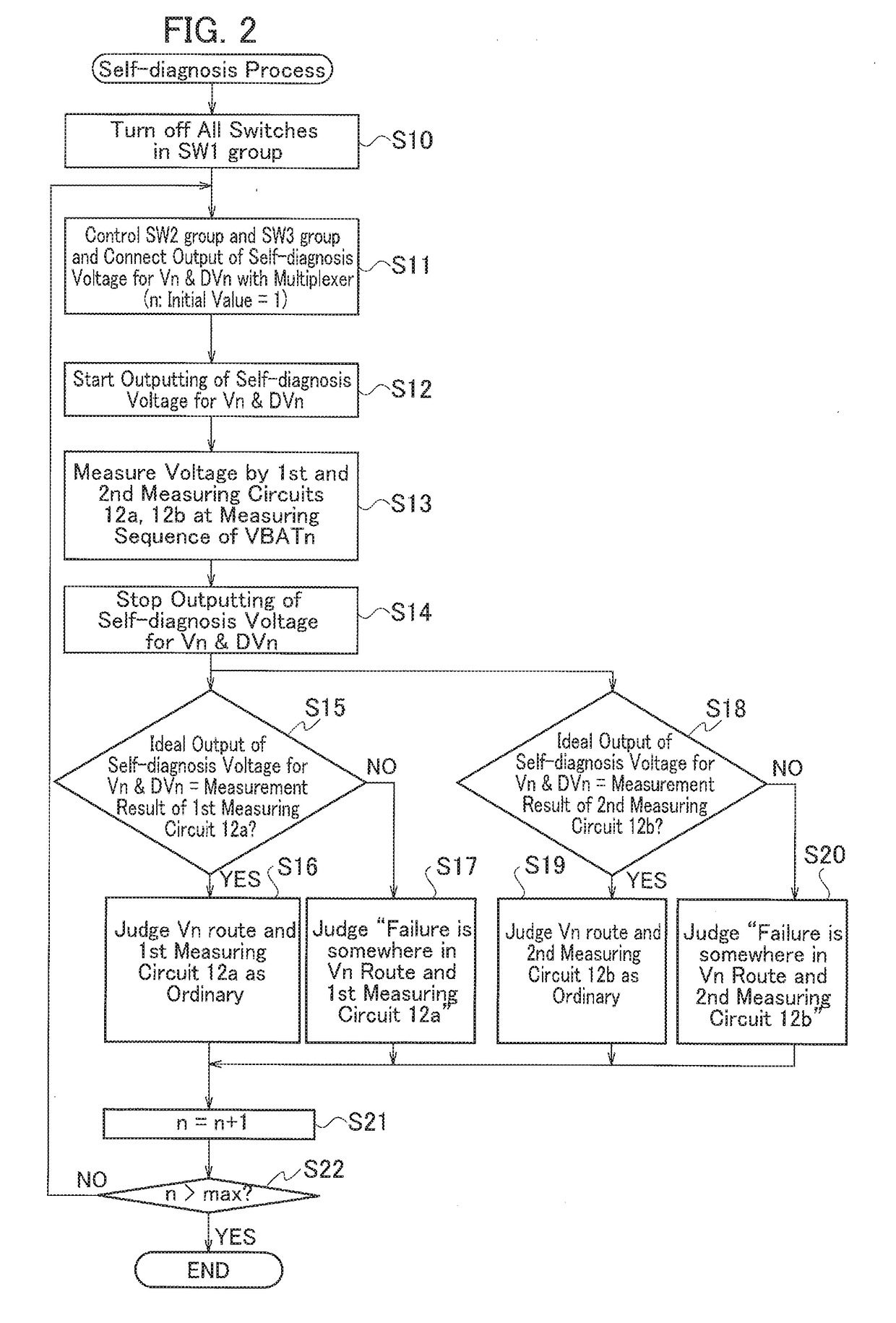
[0025]A battery monitoring system S1 according to an embodiment will be described with reference to FIGS. 1 and 2.

[0026]As illustrated in FIG. 1, the battery monitoring system S1 is configured so as to monitor a state of a battery pack including n (n: an integer) pieces of battery cells VBATn (VBAT1 to VBAT3) connected in series by plural stages and includes an input circuit IN-C to which voltage signals of the respective battery cells VBATn are inputted, a multiplexer 11 that selects a specific battery cell VBATn, whose voltage is to be detected, out of n pieces of battery cells and also selects the inputted voltage signals for outputting them, a self-diagnosis voltage generation circuit 15 that generates a self-diagnosis voltage for diagnosing a failure status of the battery monitoring system S1 itself, a first voltage measuring circuit 12a and a second voltage measuring circuit 12b that measure voltages on the basis of voltage signals in first and second routes, which have been i...


PUM


Abstract

A battery monitoring system includes a multiplexer, a self-diagnosis voltage generation circuit, a first voltage measuring circuit and a voltage measuring circuit which measure voltage signals in a first route and a second route inputted through the multiplexer, based on the self-diagnosis voltage generated from the self-diagnosis voltage generation circuit or based on the voltages of battery cells outputted from the input circuit, a comparator which compares measurement results of the first and second voltage measuring circuits, and a control unit which judges the presence / absence of a failure in a measuring route connected to the first voltage measuring circuit or the second voltage measuring circuit and the presence / absence of a failure of the first voltage measuring circuit itself or the second voltage measuring circuit itself, based on a comparison result by the comparator and which controls the input circuit, the multiplexer, the comparator, and the self-diagnosis voltage generation circuit.

Description

CROSS REFERENCE TO REBATED APPLICATION[0001]The present application is based on, and claims priority from Japanese Patent Application No. 2016-143139, filed Jul. 21, 2016, the disclosure of which is hereby incorporated by reference herein in its entirety.TECHNICAL FIELD[0002]The present application relates to a battery monitoring system for monitoring the states of battery cells constituting a battery pack.BACKGROUND ART[0003]In a hybrid vehicle, an electric vehicle, or the like, a driving power is obtained since a motor is driven by electric power accumulated in a secondary battery such as a lithium ion battery or a nickel hydrogen battery.[0004]In such a secondary battery, for example, a plurality of battery cells is mutually connected in series, thereby forming a battery pack.[0005]With charge to and discharge from respective battery cells performed repeatedly, the battery pack gradually deteriorates over time and additionally, the output voltage of each battery cell changes.[000...

Claims


Application Information

Patent Timeline
IPC IPC(8): G01R31/36
CPCG01R31/3651G01R31/362G01R31/3658B60L3/0046G01R35/00B60L3/12B60L2240/547B60L58/10G01R31/367G01R31/396Y02T10/70G01R31/3835
Inventor IZAWA, TAKAAKI
Owner YAZAKI CORP
Why Eureka
Try Eureka