
Ophthalmic devices and related methods

Inactive Publication Date: 2018-02-01
ELWHA LLC
View PDF2 Cites 1 Cited by
  • Summary
  • Abstract
  • Description
  • Claims
  • Application Information

AI Technical Summary

Benefits of technology

This patent relates to systems and methods for using ophthalmic devices with switchable lenses that can change their optical properties using electric fields. The devices also include charging electrical circuitry and transfer electrical circuitry for controllably transferring electrical energy between the charging circuitry and the switchable lens. The devices and methods can be used to modify the optical properties of the switchable lens without needing to discharge the electric field when it is decreased. The technical effect of this patent is to provide a more efficient and controllable method for applying electric fields to switchable lenses to adjust their optical properties.

Problems solved by technology

Such configurations can be limited to focusing either on near or far vision without selectively modifiable adjustment therebetween.

Method used


Image

  • Ophthalmic devices and related methods
  • Ophthalmic devices and related methods
  • Ophthalmic devices and related methods

Examples


Embodiment Construction

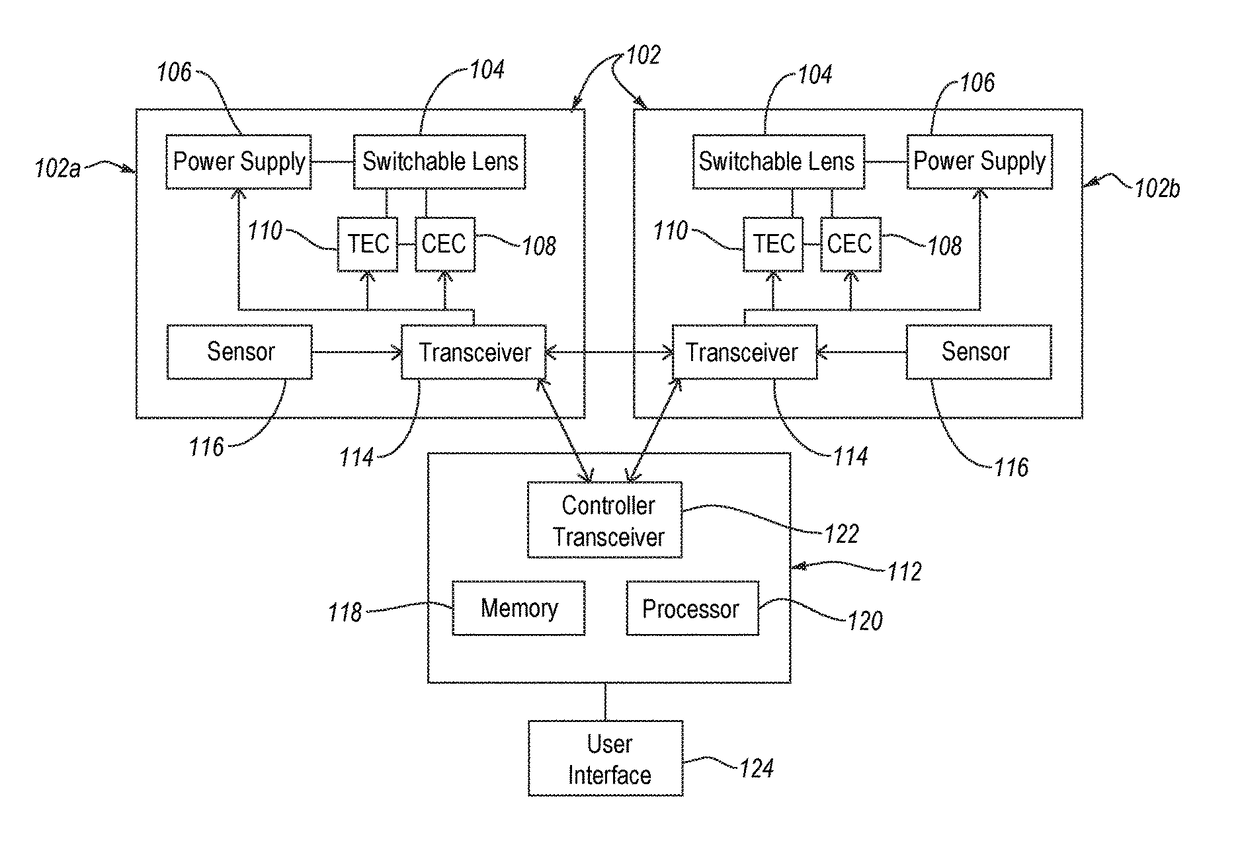
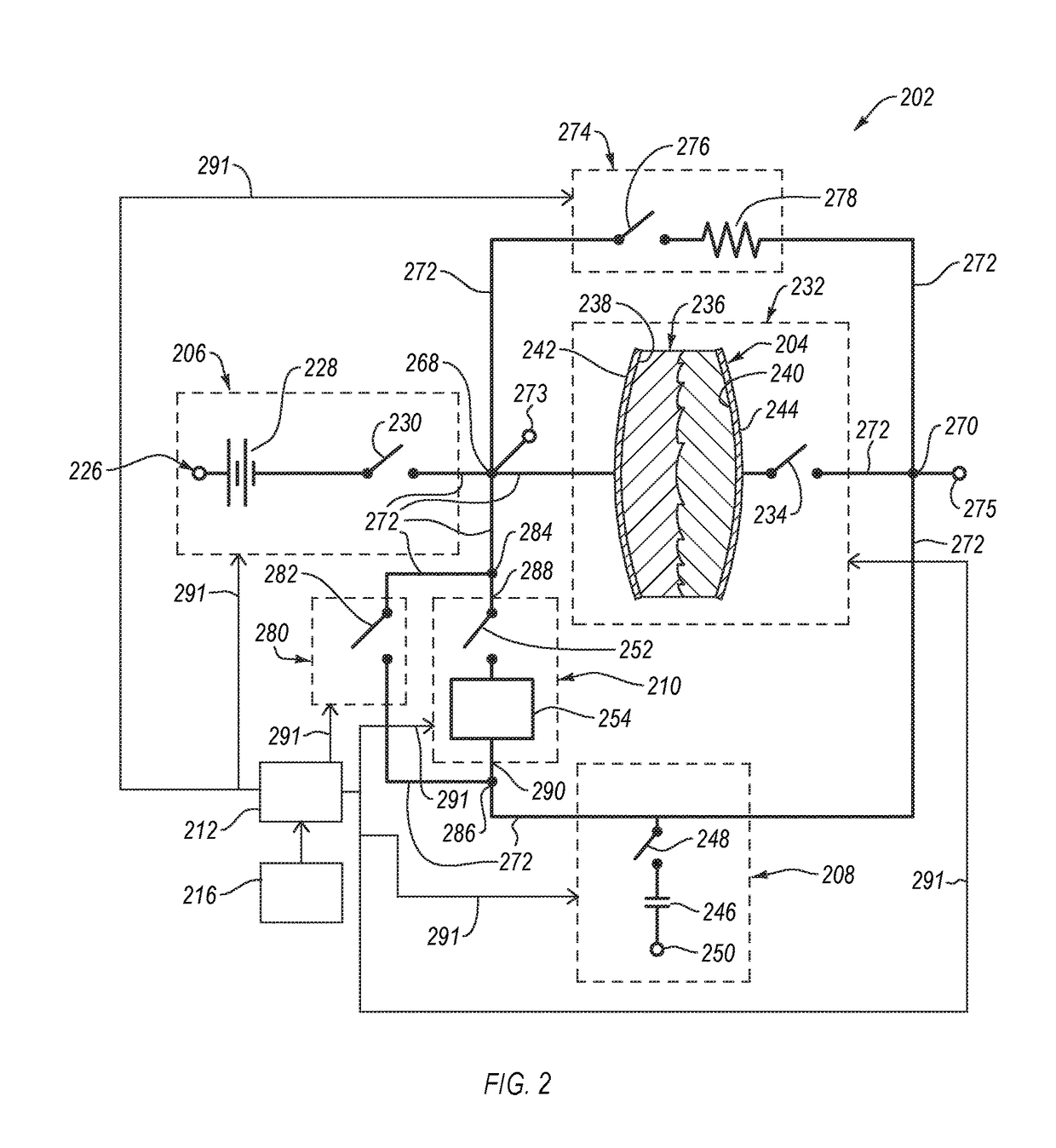
[0021]Embodiments disclosed herein relate to systems including at least one ophthalmic device and methods of using the system. The at least one ophthalmic device includes at least one switchable lens therein that includes at least one electro-optical material. The at least one electro-optical material is configured to change at least one optical property thereof responsive to an electric field. The at least one ophthalmic device also includes at least one charging electrical circuitry (“CEC”). The CEC is electrically coupled to the at least one switchable lens and is configured to receive electrical energy from or provide electrical energy to the at least one switchable lens. As such, the electrical energy used to apply an electric field to the at least one electro-optical material does not need to be discharged or otherwise dissipated from the at least one ophthalmic device when the electric field applied to the at least one electro-optical material is decreased. The ophthalmic dev...


PUM


Abstract

Embodiments disclosed herein relate to systems including at least one ophthalmic device and methods of using the system. The ophthalmic device includes at least one switchable lens therein that includes at least one electro-optical material. The ophthalmic device also includes at least one charging electrical circuitry. The charging electrical circuitry is electrically coupled to the switchable lens and is configured to receive electrical energy from or provide electrical energy to the switchable lens. The ophthalmic device can also include at least one transfer electrical circuitry that can be coupled to and configured to transfer electrical energy between the charging electrical circuitry and the switchable lens. The ophthalmic device can also include at least one controller operably coupled to at least the charging electrical circuitry and the transfer electrical circuitry. The controller can be configured to at least partially control the charging electrical circuitry and the transfer electrical circuitry.

Description

[0001]If an Application Data Sheet (ADS) has been filed on the filing date of this application, it is incorporated by reference herein. Any applications claimed on the ADS for priority under 35 U.S.C. §§119, 120, 121, or 365(c), and any and all parent, grandparent, great-grandparent, etc. applications of such applications, are also incorporated by reference, including any priority claims made in those applications and any material incorporated by reference, to the extent such subject matter is not inconsistent herewith.CROSS-REFERENCE TO RELATED APPLICATIONS[0002]The present application claims the benefit of the earliest available effective filing date(s) from the following listed application(s) (the “Priority Applications”), if any, listed below (e.g., claims earliest available priority dates for other than provisional patent applications or claims benefits under 35 USC §119(e) for provisional patent applications, for any and all parent, grandparent, great-grandparent, etc. applica...

Claims


Application Information

Patent Timeline
IPC IPC(8): G02C7/08A61F2/16G02C7/12G02C7/04G02C7/10
CPCG02C7/083G02C7/04G02C7/101G02C7/12G02C7/022G02C2202/20G02C2202/16A61F2002/1681A61F2/1624A61F2/16
Inventor HYDE, RODERICK A.MARSHALL, JOHNTEGREENE, CLARENCE T.ZALDIVAR, ROGERZALDIVAR, ROBERTO
Owner ELWHA LLC
Learn More