
Optical element driving mechanism

Active Publication Date: 2020-10-01
TDK TAIWAN
View PDF0 Cites 2 Cited by
  • Summary
  • Abstract
  • Description
  • Claims
  • Application Information

AI Technical Summary

Benefits of technology

The present invention is about a mechanism for driving an optical element to change its optical properties and achieve the effect of optical zoom. It includes an optical element module, a driving assembly, a movable member, and a fixed assembly. The driving assembly generates an electromagnetic force to move the movable member relative to the fixed assembly, which causes the optical element to deform and change its optical properties. This results in the flow of liquid to the optical element, which causes it to change its optical properties and achieve the effect of optical zoom.

Problems solved by technology

However, although the existing driving mechanism can achieve the aforementioned functions of photographing or video recording, they still cannot meet all the needs of miniaturization.

Method used


Image

  • Optical element driving mechanism
  • Optical element driving mechanism
  • Optical element driving mechanism

Examples


Embodiment Construction

[0045]In the following detailed description, for the purposes of explanation, numerous specific details and embodiments are set forth in order to provide a thorough understanding of the present disclosure. The specific elements and configurations described in the following detailed description are set forth in order to clearly describe the present disclosure. It will be apparent, however, that the exemplary embodiments set forth herein are used merely for the purpose of illustration, and the inventive concept can be embodied in various forms without being limited to those exemplary embodiments. In addition, the drawings of different embodiments can use like and / or corresponding numerals to denote like and / or corresponding elements in order to clearly describe the present disclosure. However, the use of like and / or corresponding numerals in the drawings of different embodiments does not suggest any correlation between different embodiments. The directional terms, such as “up”, “down”...


PUM


Abstract

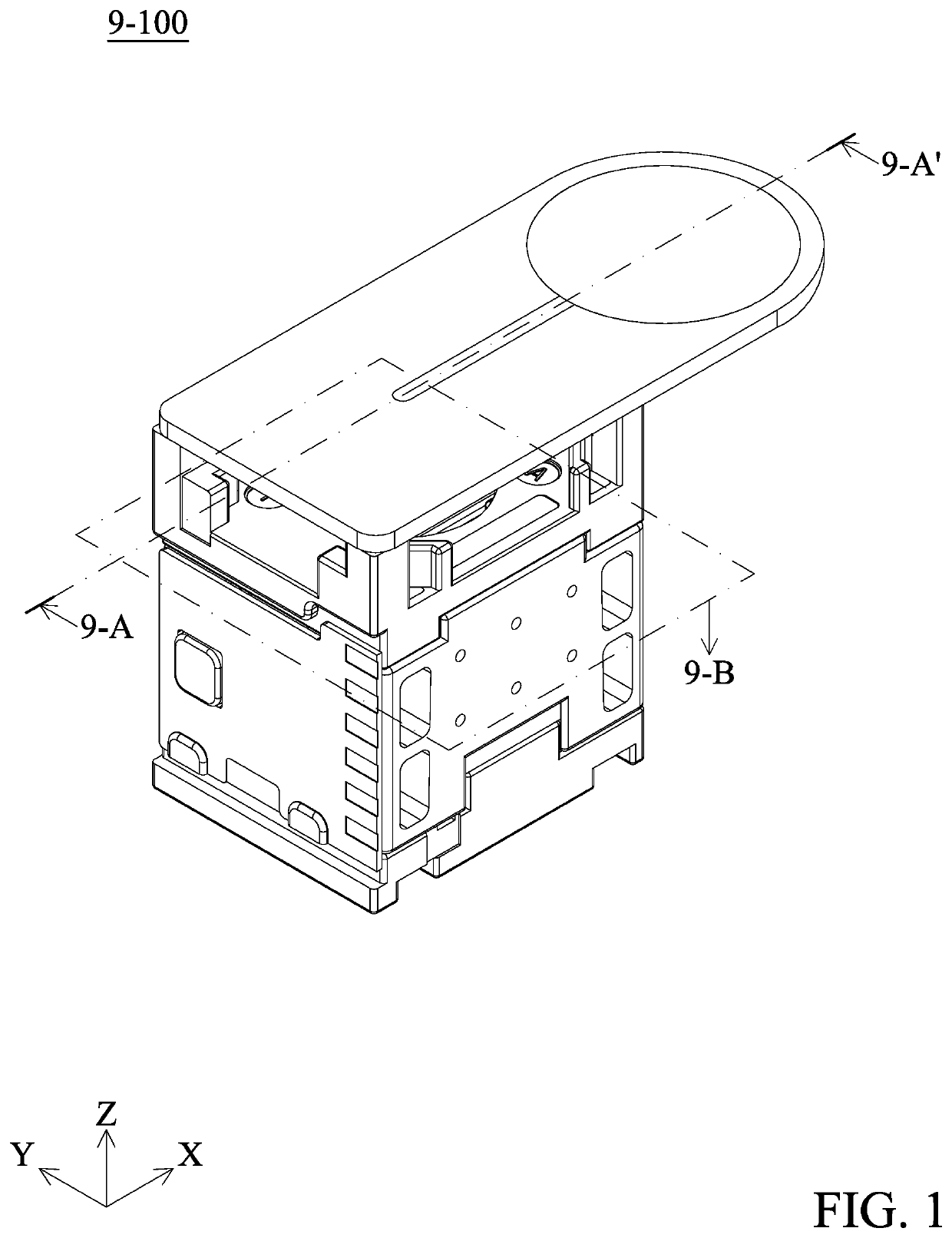
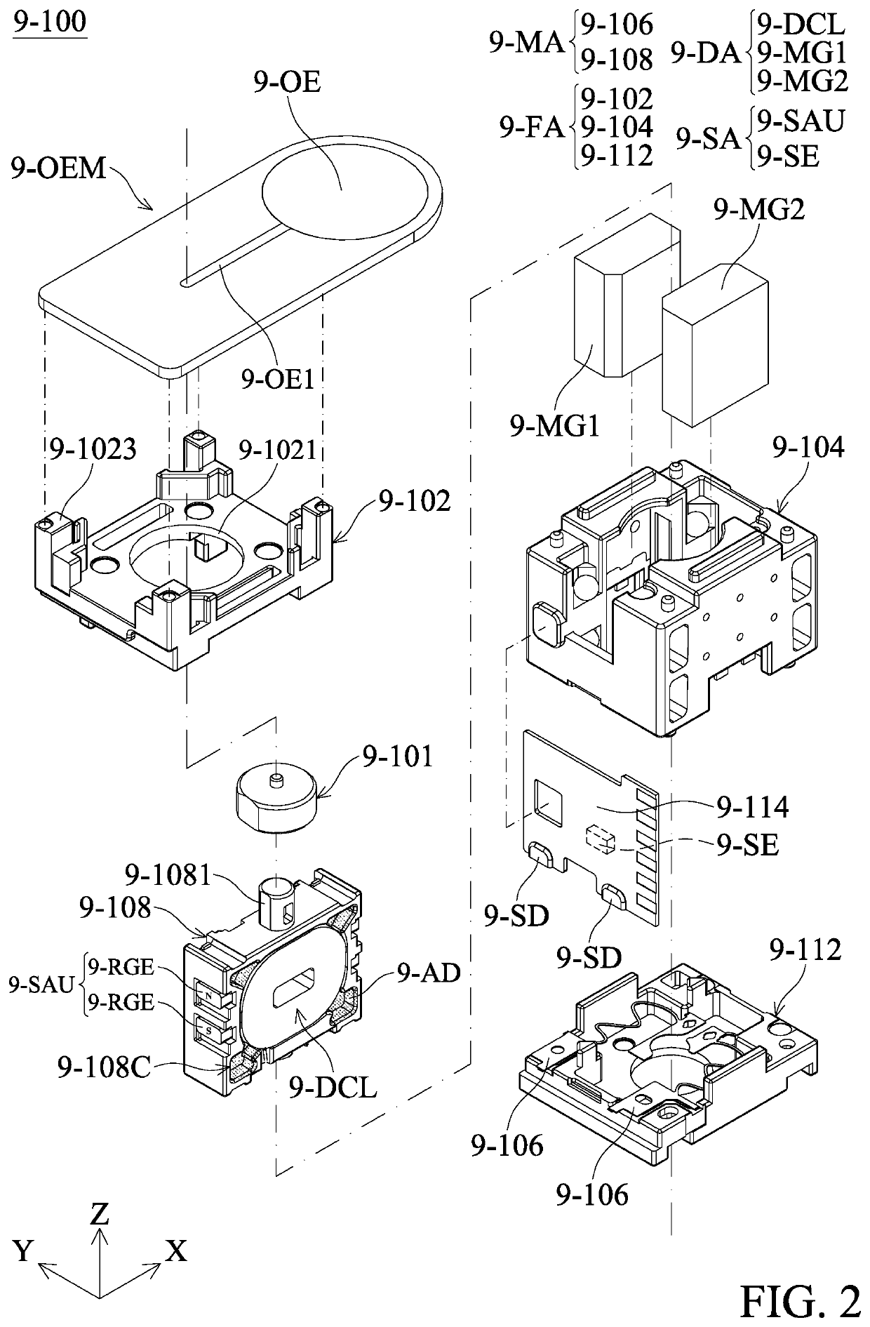
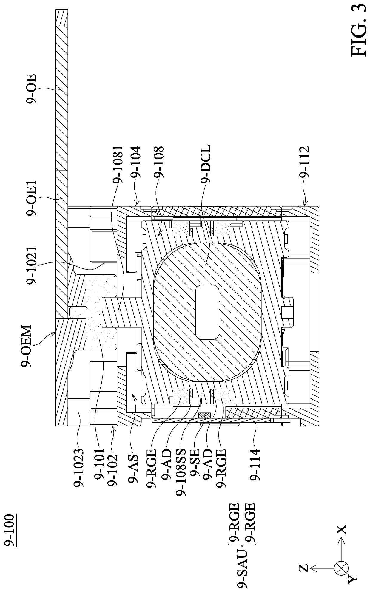
An optical element driving mechanism is provided and includes a fixed assembly, a movable assembly, a driving assembly, and a position-sensing assembly. The movable assembly corresponds to an optical element, and the movable assembly is movable relative to the fixed assembly. The driving assembly is configured to drive the movable assembly to move relative to the fixed assembly. The position-sensing assembly is configured to sense the movement of the movable assembly relative to the fixed assembly, and the position-sensing assembly includes a sensed unit and a sensing element. The sensing element corresponds to the sensed unit. The sensed unit has a plurality of reference magnetic elements arranged in a first direction, the sensed unit and the sensing element are arranged in an arrangement direction, and the first direction is not parallel to the arrangement direction.

Description

CROSS REFERENCE TO RELATED APPLICATIONS[0001]This application claims the benefit of U.S. Provisional Application No. 62 / 825,538, filed Mar. 28, 2019, and European Patent Application No. 19218902.5, filed Dec. 20, 2019, the entirety of which are incorporated by reference herein.BACKGROUND OF THE DISCLOSUREField of the Disclosure[0002]The present disclosure relates to an optical element driving mechanism, and in particular it relates to an optical element driving mechanism having a liquid lens.Description of the Related Art[0003]As technology has progressed, many kinds of electronic devices such as smartphones have begun to include the functionality of digital photography or video recording. A user can operate an electronic device to capture various images with a camera module that is included in the electronic device.[0004]The design trend of today's electronic devices is toward miniaturization, meaning that the various components of a camera module or its structure must also be cont...

Claims


Application Information

Patent Timeline
IPC IPC(8): G02B7/02G02B7/28G02B27/64
CPCG02B27/64G02B7/282G02B7/02G02B3/14G02B7/102G02B27/646H02K41/0356
Inventor HSIAO, YI-CHENGHU, CHAO-CHANGCHANG, CHE-WEISONG, SIN-JHONG
Owner TDK TAIWAN
Learn More