

Discrimination Medium And Discrimination Method Therefor
- Summary
- Abstract
- Description
- Claims
- Application Information
AI Technical Summary
Benefits of technology
Problems solved by technology
Method used
Image

Examples
first embodiment
Function of First Embodiment
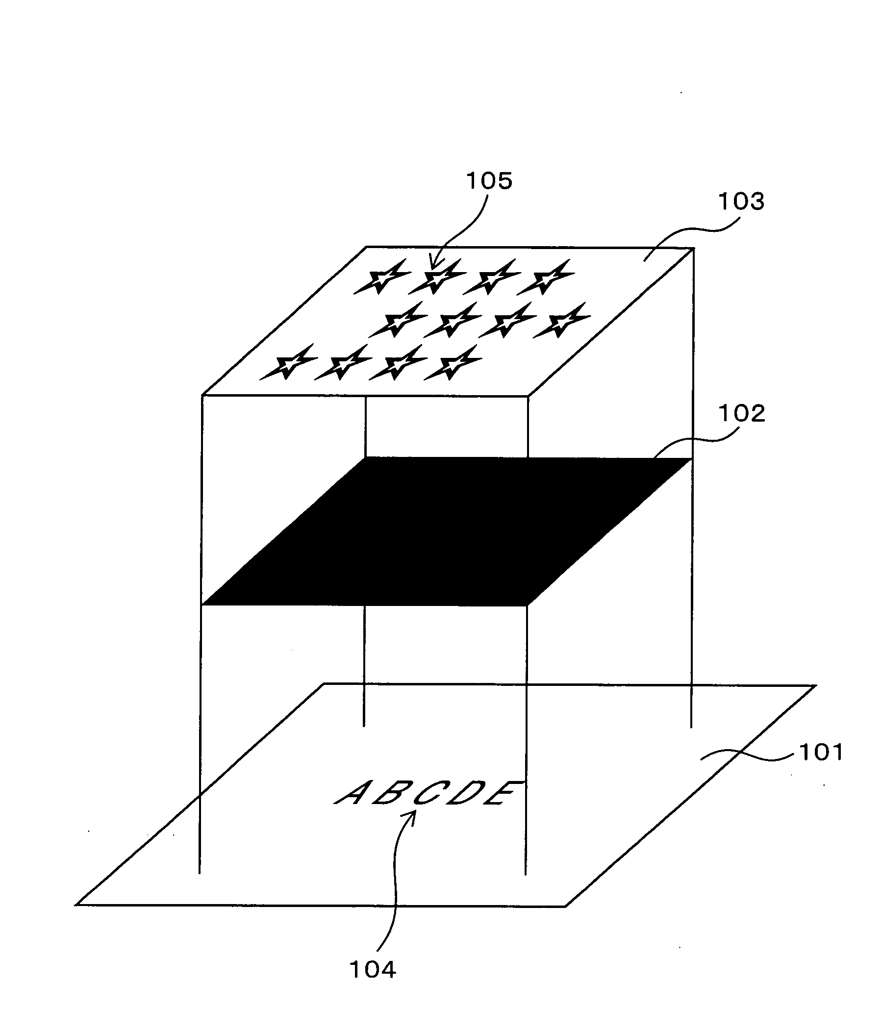
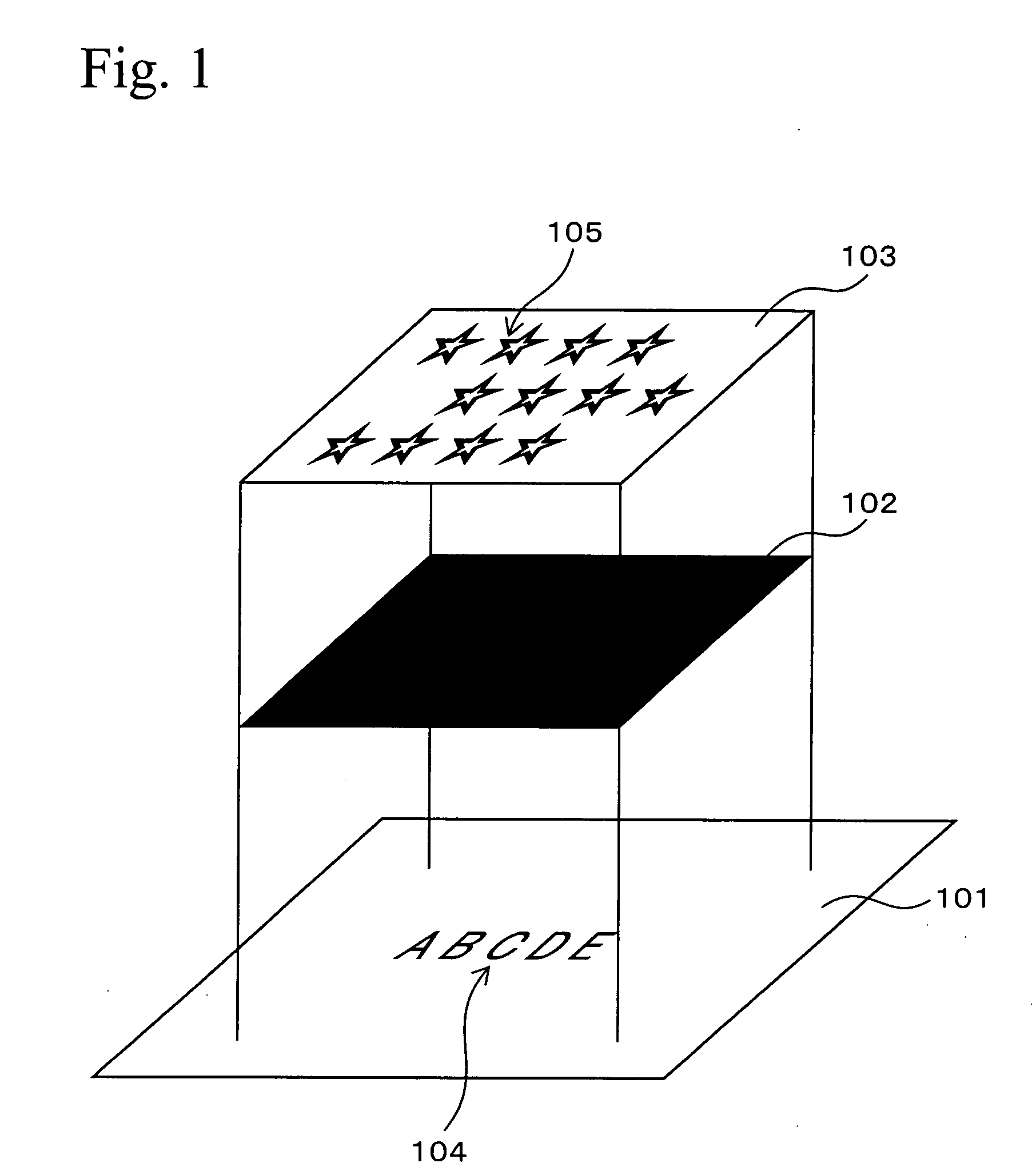
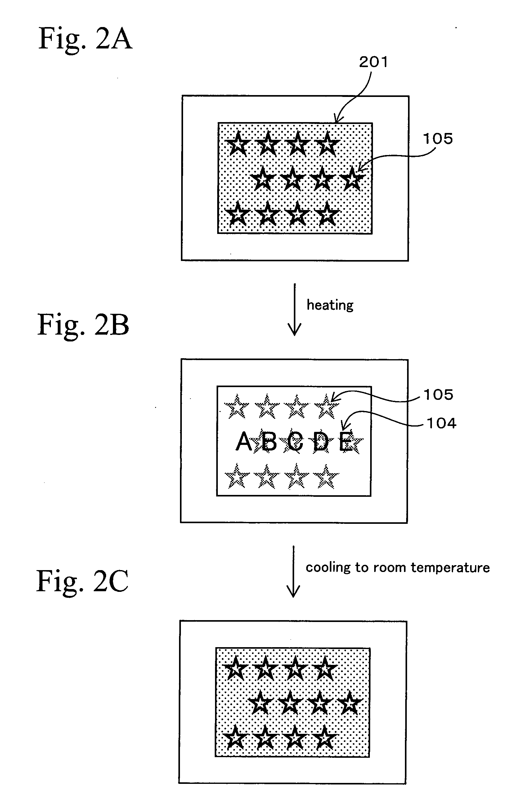
[0072]FIGS. 2A, 2B, and 2C are schematic views for explaining visual effects of the discrimination medium of the present invention. First, at ordinary temperature (25° C.), the case of viewing the discrimination medium shown in FIG. 1 from the side of the cholesteric liquid crystal layer 103 will be explained. In this case, because the thermosensitive ink layer 102 is black, only a right-handed circularly polarized light in red that is reflected at the cholesteric liquid crystal layer 103 is visible. Specifically, the figure of the hologram 105 tinged with red with a metallic luster is observed.
[0073] This condition is shown in FIG. 2A. FIG. 2A shows the hologram 105 tinged with red with a metallic luster in the background 201 of the red with the metallic luster.
[0074] In this condition, as the viewing angle increases, the figure of the hologram 105 tinged with a metallic luster is seen to shift from red to colors of the shorter wavelengths.
[0075] In t...
second embodiment
2. Second Embodiment
[0107] A multilayer film formed by laminating plural light transparent films having different refractive indexes is used instead of the cholesteric liquid crystal layer shown in the First Embodiment.
[0108] A multilayer film in which light transparent films made from polyethylene-2,6-naphthalate and light transparent films made from copolyethylene terephthalate are alternately laminated may be mentioned as a multilayer film. The material for the multilayer film is not limited to the above material. Not only the films of the different kind of materials, but also the films of the same kind of materials having different refractive indexes may be combined together. An anisotropic multilayer film may be formed by changing the draw rate in the lengthwise direction and the crosswise direction. Anisotropy shows different color changes in the lengthwise direction and the crosswise direction by tilting the discrimination medium.
[0109] The multilayer film is formed with a ...
third embodiment
3. Third Embodiment
[0110] A photochromic ink may be used instead of the thermosensitive ink layer shown in First Embodiment. The photochromic ink is, for example, an ink which changes color when it is irradiated with ultraviolet light.
[0111] As a photochromic ink, an ink which is transparent under ordinary white light and changes to a predetermined color state (for example, black or a dark color) when it is irradiated with ultraviolet light of a predetermined wavelength and at high intensity may be mentioned.
[0112] In this case, a significant difference in appearance of the figure is due not to the heating condition explained in the First Embodiment, but due to the irradiating conditions of the ultraviolet light.
PUM
| Property | Measurement | Unit |
|---|---|---|
| Temperature | aaaaa | aaaaa |
| Color | aaaaa | aaaaa |
| Transparency | aaaaa | aaaaa |
Abstract
Description
Claims
Application Information