
Image heating apparatus and image forming apparatus

a heating apparatus and image technology, applied in the field of image forming apparatus, can solve problems such as damage to parts of the apparatus, and achieve the effect of ensuring the safety of the apparatus

Active Publication Date: 2018-02-01
CANON KK
View PDF19 Cites 12 Cited by
  • Summary
  • Abstract
  • Description
  • Claims
  • Application Information

AI Technical Summary

Benefits of technology

The invention aims to keep an apparatus safe in case of abnormal operations without having to install temperature detection devices in each heat-generating block. This makes it difficult for the apparatus to overheat and potentially cause damage or injury.

Problems solved by technology

When the temperature of the non-sheet-passing portion is too high, parts in the apparatus may be damaged.

Method used


Image

  • Image heating apparatus and image forming apparatus
  • Image heating apparatus and image forming apparatus
  • Image heating apparatus and image forming apparatus

Examples


embodiment 1

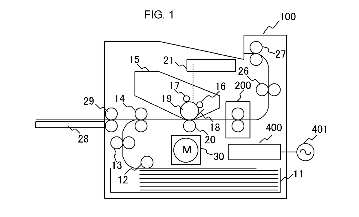
[0018]FIG. 1 is a schematic cross-sectional view of an image forming apparatus (hereinafter referred to as a laser printer) 100 which uses an electrophotographic recording technique. Embodiments of an image forming apparatus to which the present invention can be applied include a copying machine, a printer, and the like which uses an electrophotographic system or an electrostatic recording system. In this example, a case in which the present invention is applied to a laser printer will be discussed.

[0019]When a print signal is generated, a scanner unit 21 emits a laser beam modulated according to image information to scan a photosensitive member 19 which is charged to a predetermined polarity by a charging roller 16. In this way, an electrostatic latent image is formed on the photosensitive member 19. Toner is supplied from a developing device 17 to the electrostatic latent image and a toner image corresponding to the image information is formed on the photosensitive member 19. The ...

embodiment 2

[0046]Embodiment 2 of the present invention will be described. In Embodiment 2, the number of divisions and dividing positions of the heat generating resistor 302 of the heater 300 described in Embodiment 1 is changed. The same constituent elements as those of Embodiment 1 will be denoted by the same reference numerals and the description thereof will not be provided.

[0047]FIG. 6A illustrates a cross-sectional view in a transverse direction of a heater 600. The number of divisions is 7 as compared to the heater 300 of Embodiment 1. The heater 600 includes heat generating resistors 602a and 602b that are provided between conductors 301 and 603 to generate heat according to an electric power supplied via the conductors 301 and 603. The heat generating resistor 602a is disposed on the upstream side in the conveying direction of the recording sheet P and the heat generating resistor 602b is disposed on the downstream side. Hereinafter, the heat generating resistors 602a and 602b will be...


PUM


Abstract

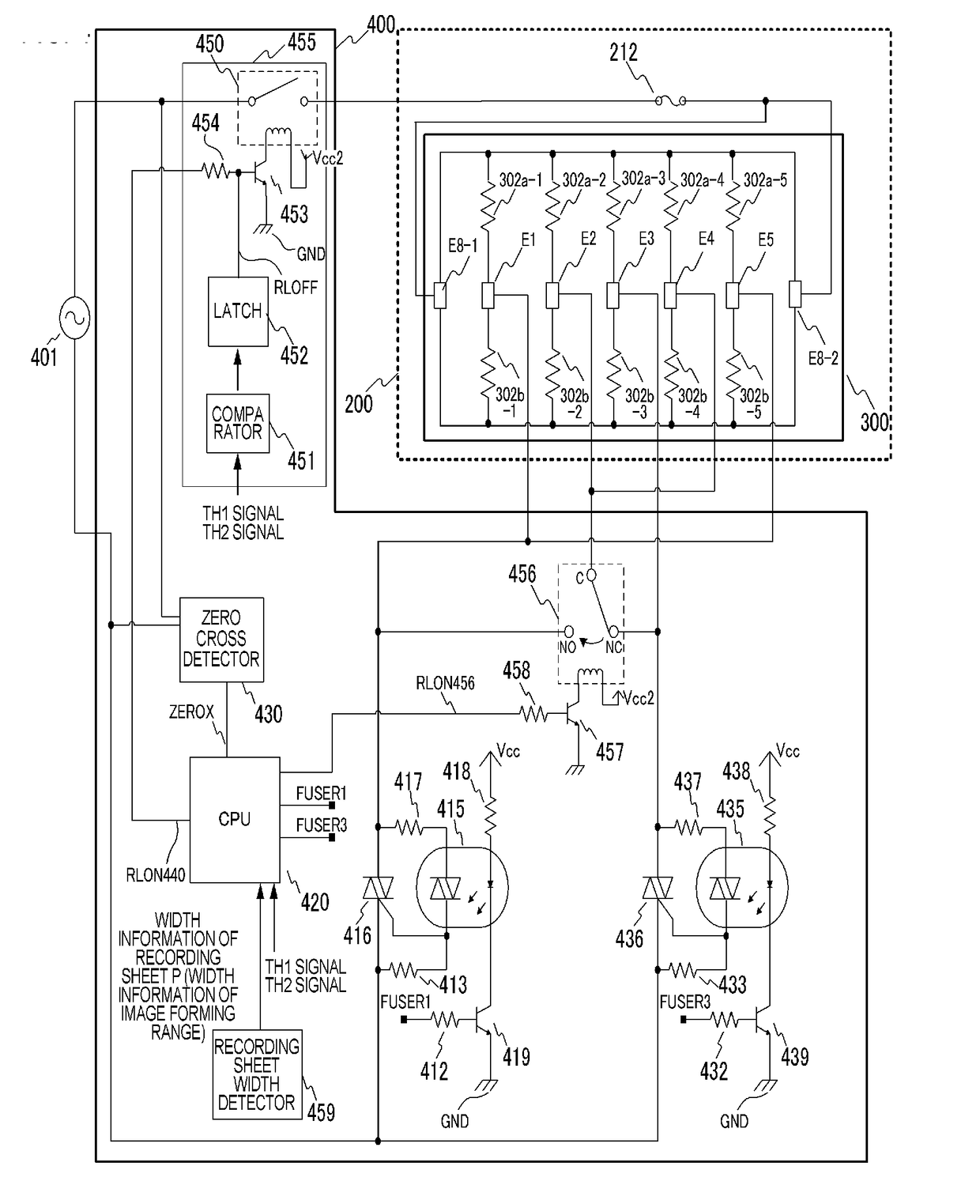
An apparatus includes a first and second driving circuits that energize a first and third heat generating blocks; a first and second temperature detection members that detect each temperature of the first and third heat generating blocks; a control portion that controls the first and second driving circuits according to at least one of the temperatures detected by the first and second temperature detection members; and a connection switching portion that selectively connects any one of the first and second driving circuits to a second heat generating block according to a switching instruction from the control portion. The control portion controls energization of the second heat generating block together with a heat generating block which is energized by the driving circuit connected to the second heat generating block.

Description

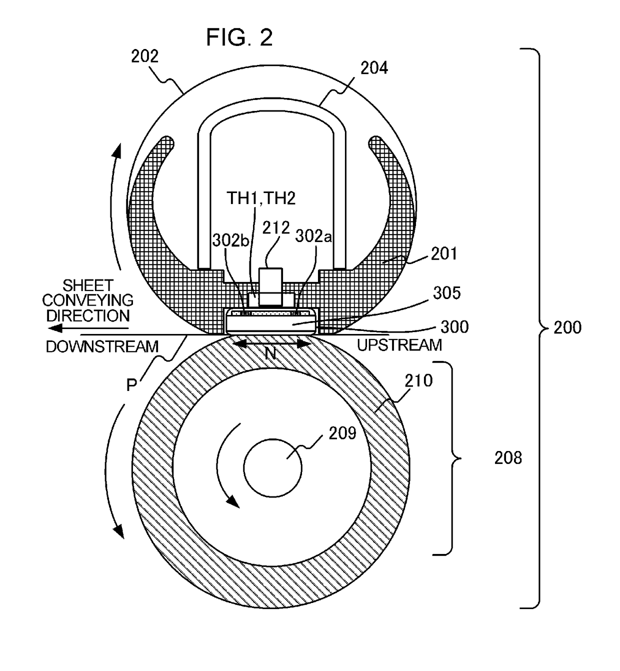
BACKGROUND OF THE INVENTIONField of the Invention[0001]The present invention relates to an image forming apparatus such as a copying machine or a printer which uses an electrophotographic system or an electrostatic recording system. The present invention also relates to an image heating apparatus such as a fixing unit mounted on an image forming apparatus, and a gloss applying apparatus which heats the toner image fixed on a recording material again in order to improve the gloss level of the toner image.Description of the Related Art[0002]In an image forming apparatus which uses an electrophotographic system, an electrostatic recording system, or the like, is provided with an image heating apparatus serving as a fixing unit to heat and fix a toner image formed on a recording material. An example of such an image heating apparatus is an apparatus that includes a fixing film (also referred to as an endless belt), a heater that makes contact with an inner surface of the fixing film, an...

Claims


Application Information

Patent Timeline
IPC IPC(8): G03G15/20
CPCG03G15/2039G03G15/2014G03G15/2053G03G2215/2019G03G15/2075G03G15/2089H05B3/0095G03G15/2028G03G15/2042G03G2215/2035H05B1/0241G03G15/2025G03G15/206
Inventor OGURA, RYOTA
Owner CANON KK
Learn More