Touch sensor panel with multi-power domain chip configuration

a multi-power domain, chip configuration technology, applied in the field of touch sensor panels, can solve problems such as and achieve the effects of reducing or eliminating stray or parasitic capacitance, improving the touch sensing performance of the system, and degrading the dynamic range of the touch sensor

Active Publication Date: 2018-02-01
APPLE INC
View PDF4 Cites 34 Cited by
  • Summary
  • Abstract
  • Description
  • Claims
  • Application Information

AI Technical Summary

Benefits of technology

[0006]As previously mentioned, parasitic or stray capacitances can exist between touch electrodes on touch sensor panels and other components of the devices in which the touch sensor panels are included, which can introduce errors and/or offsets into the touch outputs of the touch sensor panels, therefore degrading touch sensing dynamic range. The examples of the disclosure provide various touch sensing system configurations in which a touch sensing chip can be o

Problems solved by technology

As previously mentioned, parasitic or stray capacitances can exist between touch electrodes on touch sensor panels and other components of the devices in which the touch

Method used


Image

  • Touch sensor panel with multi-power domain chip configuration
  • Touch sensor panel with multi-power domain chip configuration
  • Touch sensor panel with multi-power domain chip configuration

Examples


Embodiment Construction

[0024]In the following description of examples, reference is made to the accompanying drawings which form a part hereof, and in which it is shown by way of illustration specific examples that can be practiced. It is to be understood that other examples can be used and structural changes can be made without departing from the scope of the disclosed examples.

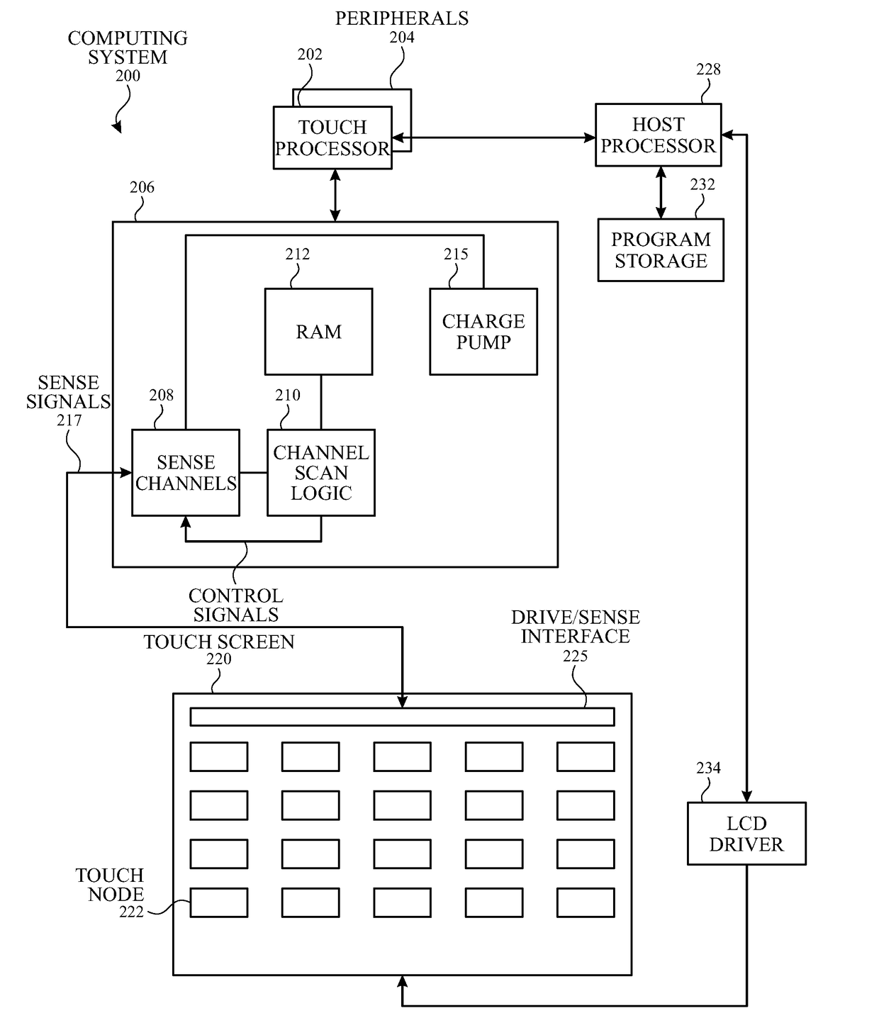
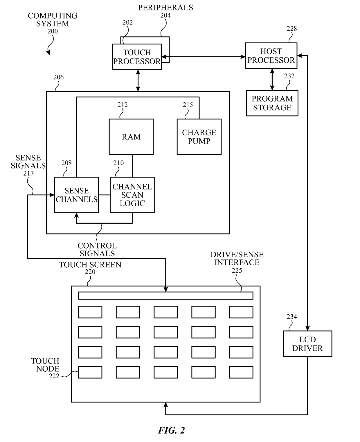
[0025]Some capacitive touch sensor panels can be formed by a matrix of substantially transparent or non-transparent conductive plates (e.g., touch electrodes) made of materials such as Indium Tin Oxide (ITO), and some touch screens can be formed by at least partially integrating touch sensing circuitry into a display pixel stackup (i.e., the stacked material layers forming the display pixels). In some cases, parasitic or stray capacitances can exist between the touch electrodes used for sensing touch on the touch sensor panels, and other components of the devices in which the touch sensor panels are included, which can be referenc...


PUM


Abstract

A touch sensing system is disclosed. The touch sensing system includes a guard signal generation chip operating in a first power domain referenced to a first voltage, the guard signal generation chip configured to generate a guard signal. A touch sensing chip operates in a second power domain, different from the first power domain, referenced to the guard signal, the touch sensing chip configured to sense touch at one or more touch electrodes included in a touch sensor panel operating in the second power domain referenced to the guard signal, and the touch sensing chip a different chip than the guard signal generation chip. A voltage regulator is configured to selectively regulate a voltage of the guard signal at the touch sensing chip.

Description

CROSS-REFERENCE TO RELATED APPLICATIONS[0001]This application is a Non-Provisional application which claims the benefit of U.S. Provisional Patent Application No. 62 / 458,925, filed Feb. 14, 2017, and U.S. Provisional Patent Application No. 62 / 399,230, filed Sep. 23, 2016, and U.S. Provisional Patent Application No. 62 / 368,798, filed Jul. 29, 2016, the contents of which are incorporated herein by reference in their entirety for all purposes.FIELD OF THE DISCLOSURE[0002]This relates generally to touch sensor panels, and more particularly to touch sensor panels in which a touch sensing chip operates in a different power domain than other chips in the touch sensing system.BACKGROUND OF THE DISCLOSURE[0003]Many types of input devices are presently available for performing operations in a computing system, such as buttons or keys, mice, trackballs, joysticks, touch sensor panels, touch screens and the like. Touch screens, in particular, are becoming increasingly popular because of their e...

Claims


Application Information

Patent Timeline
IPC IPC(8): G06F3/044G02F1/1343G02F1/1333G06F3/041
CPCG06F3/044G06F3/0418G06F3/0412G02F1/13338G02F1/1343G06F2203/04107
Inventor KRAH, CHRISTOPH H.SAUER, CHRISTIAN M.
Owner APPLE INC
Why Eureka
Try Eureka