Quick-Turn Driving Tool

a technology of driving tool and handle, which is applied in the direction of wrenches, screwdrivers, manufacturing tools, etc., can solve the problems of easy collision between the handle portion and the user's hand holding the sleeve element, and achieve the effect of facilitating description

Active Publication Date: 2018-02-08
LIOU MOU TANG
View PDF15 Cites 3 Cited by
  • Summary
  • Abstract
  • Description
  • Claims
  • Application Information

AI Technical Summary

Benefits of technology

[0028]All figures are drawn for ease of explanation of the basic teachings only; the extensions of the figures with respect to number, position, relationship, and dimensions of the parts to form the illustrative embodiments will be explained or will be within the skill of the art after the following teachings have been read and understood. Further, the exact dimensions and dimensional proportions to conform to specific force, weight, strength, and similar requirements will likewise be within the skill of the art after the following teachings

Problems solved by technology

However, when a user holds the sleeve element and rotates the main body, a collision is e

Method used


Image

  • Quick-Turn Driving Tool
  • Quick-Turn Driving Tool
  • Quick-Turn Driving Tool

Examples


first embodiment

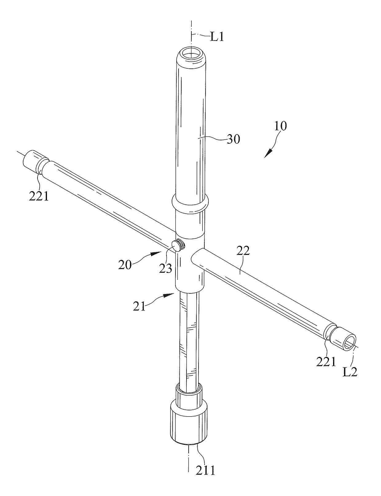
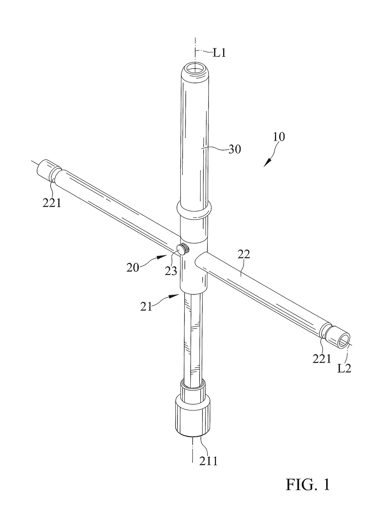
[0030]FIGS. 1-8 show a driving tool 10 of a first embodiment according to the present invention shown in the drawings. The driving tool 10 includes a body 20 and an auxiliary handle 30 rotatably mounted on the body 20.

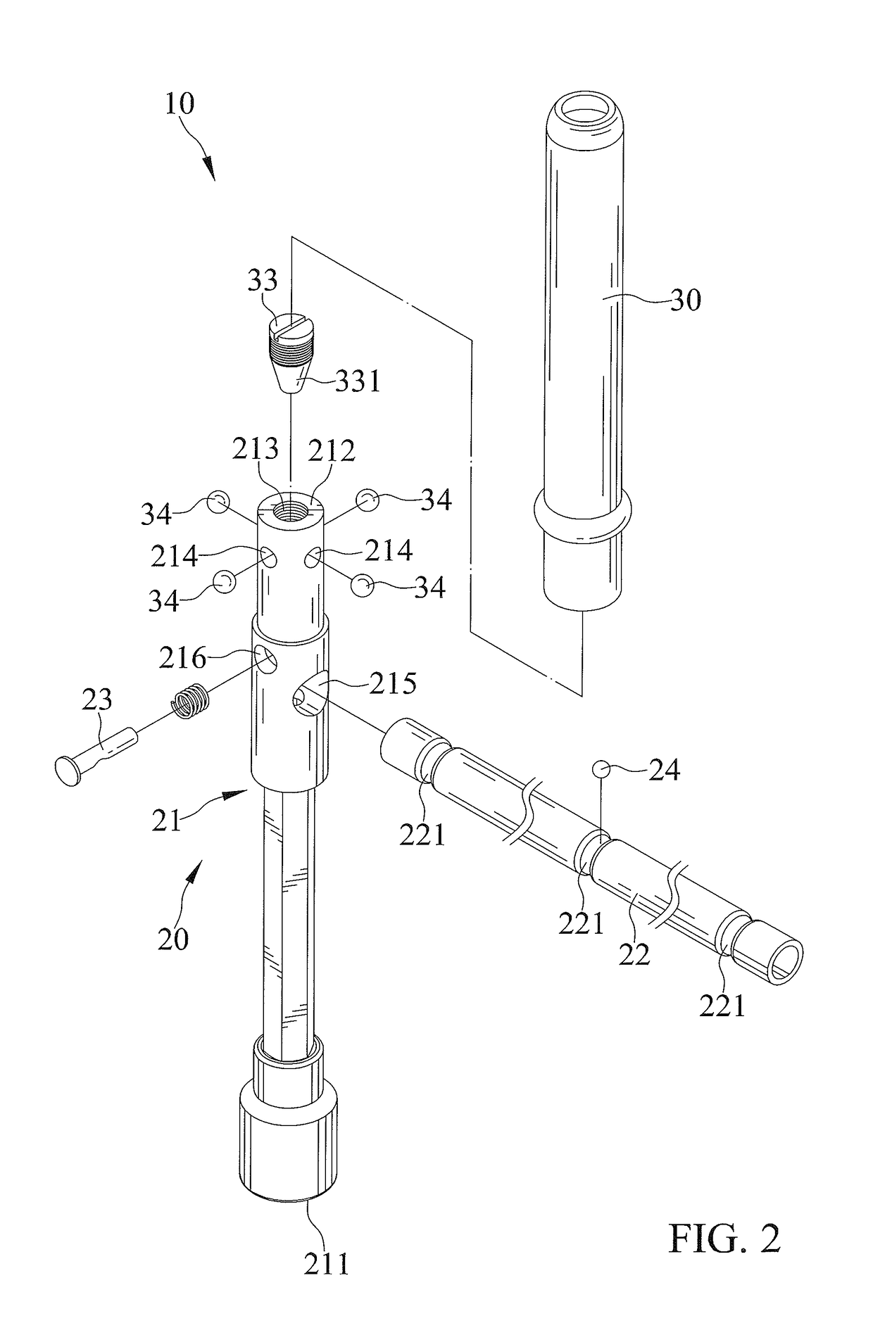
[0031]The body 20 includes a first rod 21 extending along a first axis L1, and a second rod 22 extending along a second axis L2 perpendicular to the first axis L1. The first rod 21 includes a driving end 211 and an operating end 212 spaced from the driving end 211 along the first axis L1. The first rod 21 includes an insertion hole 213 extending from the operating end 212 toward the driving end 211 along the first axis L1, and at least one receiving slot 214 extending along a radial direction perpendicular to the first axis L1. One end of the receiving slot 214 is interconnected with the insertion hole 213, and another end of the receiving slot 214 is connected to an outer periphery of the first rod 21. In the embodiment, the first rod 21 includes four receiving slots ...

second embodiment

[0040]FIGS. 9 and 10 show a driving tool 10 of a second embodiment according to the present invention shown in the drawings. The second embodiment is substantially the same as the first embodiment. The second embodiment is different from the first embodiment by that the first rod 21a includes a through hole 215a disposed between the driving end 211a and the operating end 212a and extending along the radial direction perpendicular to the first axis L1. A channel 217a is disposed between the insertion hole 213a and the through hole 215a and extends along the first axis L1. One end of the channel 217a is interconnected with the insertion hole 213a, and another end of the channel 217a is interconnected with the through hole 215a.


PUM


Abstract

A driving tool includes a body and an auxiliary handle. The body includes a first rod and a second rod perpendicular to each other. The first rod includes an insertion hole and at least one receiving slot. The second rod is mounted between two opposite ends of the first rod. The auxiliary handle includes a connection slot mounted on the body, and an engaging recess. An adjusting member is mounted in the insertion hole and movable in relation to the first rod. At least one engaging member is received in the receiving slot and the engaging recess and is abutted against the adjusting member. Thus, the auxiliary handle is freely rotatable relative to the first rod.

Description

BACKGROUND OF THE INVENTION[0001]The present invention relates to a driving tool and, more particular, to a driving tool capable of swiftly turning objects, such as nuts and bolts. U.S. Patent Publication NO. 2011 / 0079118 discloses a hand tool including a main body and a sleeve element. The sleeve element is rotatably disposed on the main body. As such, a using can hold the sleeve element while rotating the main body quickly to drive a workpiece.[0002]However, when a user holds the sleeve element and rotates the main body, a collision is easily occurred between the handle portion and the user's hand holding the sleeve element.[0003]The present invention is, therefore, intended to obviate or at least alleviate the problems encountered in the prior art.BRIEF SUMMARY OF THE INVENTION[0004]The present invention solves this need and other problems in the field of driving tools by providing a driving tool including a body and an auxiliary handle.[0005]The body includes a first rod extendi...

Claims


Application Information

Patent Timeline
IPC IPC(8): B25G1/00B25B23/16B25G1/06B25B13/06
CPCB25G1/005B25G1/063B25B23/16B25B13/06B25G1/046
Inventor LIOU, MOU-TANG
Owner LIOU MOU TANG
Why Eureka
Try Eureka