Method for Estimating a State of Charge of Batteries

Active Publication Date: 2014-07-31
MITSUBISHI ELECTRIC RES LAB INC
View PDF13 Cites 28 Cited by
  • Summary
  • Abstract
  • Description
  • Claims
  • Application Information

AI Technical Summary

Benefits of technology

[0011]Then, an adaptive SoC estimation scheme is implemented concurrently but independently to each model, with the model in each implementation assumed to be true. The intermediate SoC estimates resulting from the different models are fused in the light of a certain s

Problems solved by technology

However, accurate identification is difficult for the following reasons.
The parameters can differ from one battery to another, making identification for each battery difficult.
However, the convergence, and as a result, the accuracy, are difficult to guarantee In another method,

Method used


Image

  • Method for Estimating a State of Charge of Batteries
  • Method for Estimating a State of Charge of Batteries
  • Method for Estimating a State of Charge of Batteries

Examples


Embodiment Construction

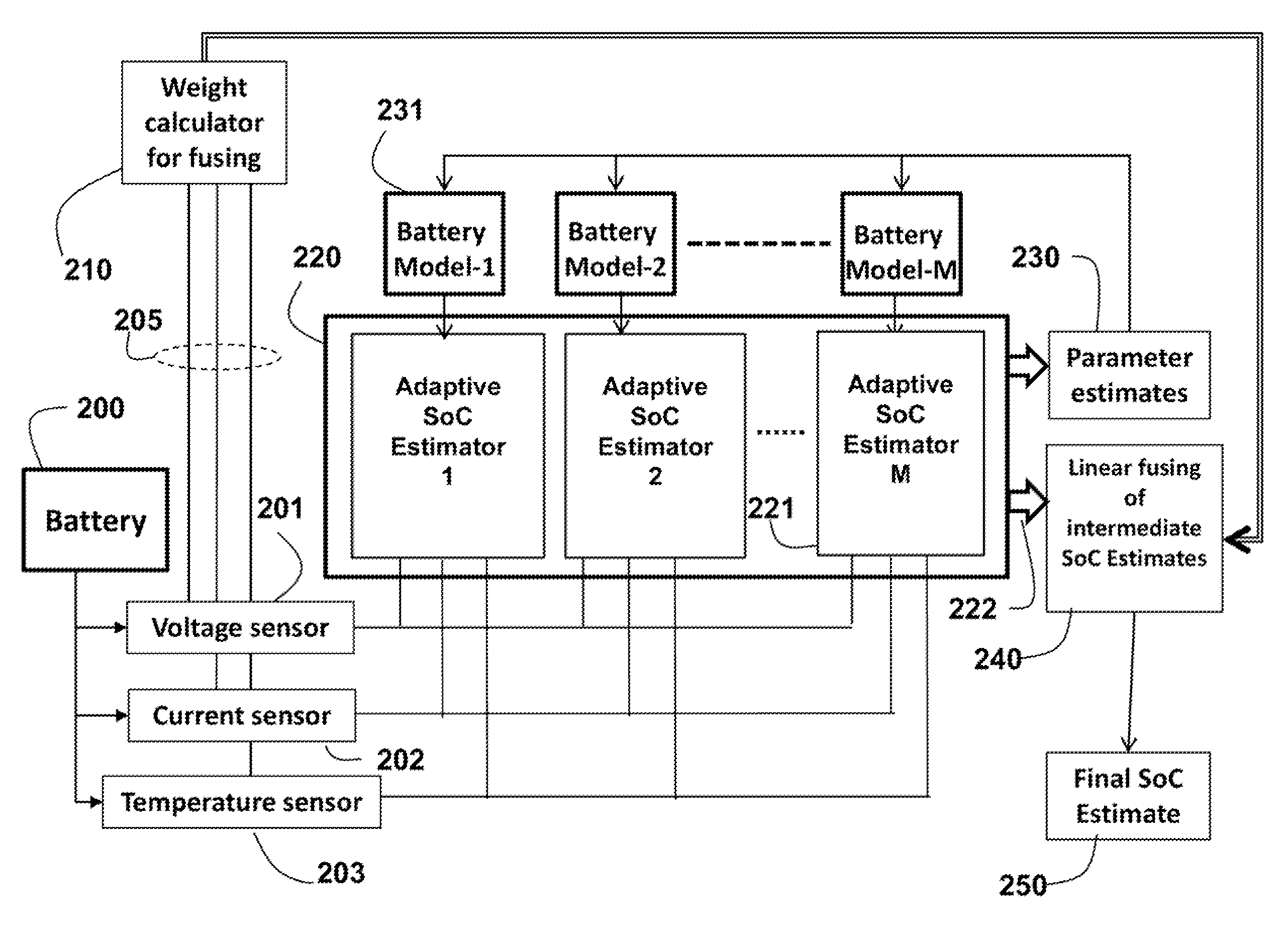
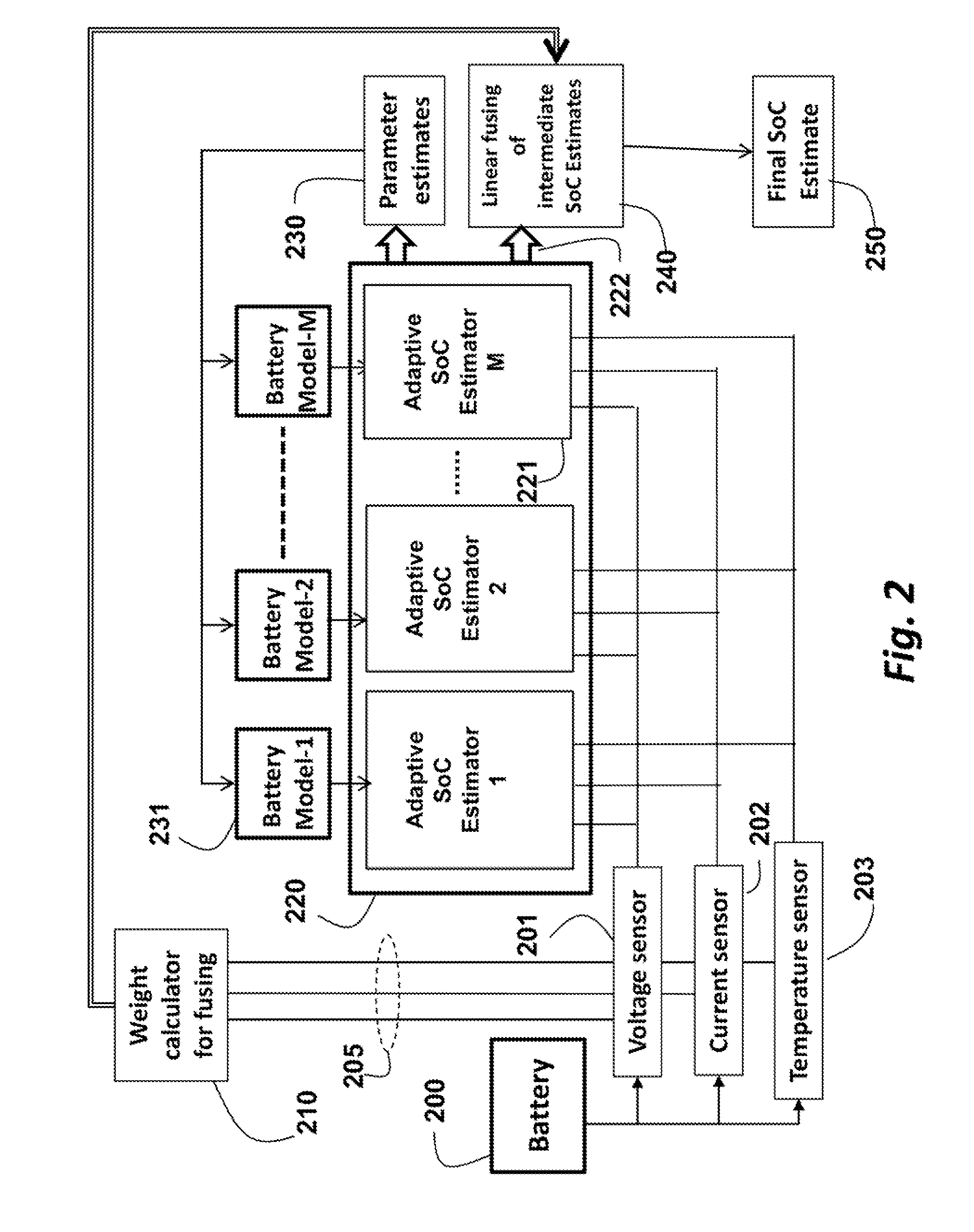
[0015]FIG. 2 shows a structure of a multimodel adaptive SoC (MM-AdaSoC) system according to embodiments of the invention. A battery 200 is connected to a voltage sensor 102, a current sensor 102, and a temperature sensor 103. The battery can operates according to lithium-ion chemistries, although it is understood that the invention can be used with other types of rechargeable batteries.

[0016]A weight calculator 210 is used for weighting of output of the sensors 201-203 that are used to fuse 240 intermediate SoC estimates. The estimator 220 includes a set of two or more (multiple) adaptive estimators 221, 1, . . . , M. There is a corresponding battery model 231 for each adaptive estimator. The estimator 220 determines parameters 230 for the models 231. The intermediate SoC estimates that are output by the adaptive estimators 221 are fused 240 to obtain a final estimate of the SoC 250.

[0017]Each parallel state-of-charge estimator 221 is based on different models 231. Each estimator us...


PUM


Abstract

A method estimates a state-of-charge (SoC) of a battery by constructing a set of two or more battery models. Each battery model is associated with an adaptive SOC estimator. A set of intermediate SOCs is estimated using the models and the associate adaptive SoC estimators. Then, the set of intermediate SoCs are fused to obtain a final SoC of the battery.

Description

RELATED APPLICATION[0001]This Application is a Continuation-in-Part of U.S. Patent Applicant, Ser. No. 13 / 752,666, “Method for Estimating State of Charge for Lithium-ion Batteries,” filed by Wang, Jan. 29, 2013, incorporated herein by reference. The related Application is an adaptive approach for SoC estimation using a single battery model.FIELD OF THE INVENTION[0002]This invention relates in general to rechargeable batteries, and in more particular to state-of-charge estimation of batteries with Lithium-ion chemistries.BACKGROUND OF THE INVENTION[0003]Many power applications require a well-designed battery management system (BMS) for operational safety and performance. The BMS monitors a current status of a battery, and regulates charging and discharging processes. One fundamental function is to estimate a state-of-charge (SoC) of the battery, i.e., a ratio of the current battery capacity over the maximal capacity.[0004]In SoC estimation, one notable trend is an increasing emphasis...

Claims


Application Information

Patent Timeline
IPC IPC(8): G01R31/36
CPCG01R31/3606G01R31/3648G01R31/367G01R31/3842
Inventor SAHINOGLU, ZAFERFANG, HUAZHENWANG, YEBIN
Owner MITSUBISHI ELECTRIC RES LAB INC
Why Eureka
Try Eureka