Energy storage device management apparatus, energy storage device module, vehicle, and energy storage device management method

a technology of energy storage device and management apparatus, which is applied in the direction of secondary cell servicing/maintenance, instruments, etc., can solve the problems of increasing cumulative error, reducing the frequency of application of ocv method, and large error in soc estimation, so as to reduce the error of soc estimation and improve the accuracy of soc estimation

Active Publication Date: 2020-07-14
GS YUASA INT LTD
View PDF54 Cites 1 Cited by
  • Summary
  • Abstract
  • Description
  • Claims
  • Application Information

AI Technical Summary

Benefits of technology

[0005]When an energy storage device has a plateau region with a small OCV variation in the SOC-OCV characteristics, an SOC estimation by the OCV method in this plateau region causes a large error in the SOC estimation. To solve this problem, it is thought that the OCV method is used only in a region with an inclination of an OCV variation in the SOC-OCV characteristics in the SOC estimation. In this case, the application of the OCV method is limited to the case with an inclination of an OCV variation, which reduces the frequency of the application of the OCV method and eventually increases a cumulative error caused by the current integration method.
[0008]According to the techniques disclosed in this description, the SOC estimation error is reduced and the SOC estimation accuracy is improved in an energy storage device.

Problems solved by technology

When an energy storage device has a plateau region with a small OCV variation in the SOC-OCV characteristics, an SOC estimation by the OCV method in this plateau region causes a large error in the SOC estimation.
In this case, the application of the OCV method is limited to the case with an inclination of an OCV variation, which reduces the frequency of the application of the OCV method and eventually increases a cumulative error caused by the current integration method.

Method used


Image

  • Energy storage device management apparatus, energy storage device module, vehicle, and energy storage device management method
  • Energy storage device management apparatus, energy storage device module, vehicle, and energy storage device management method
  • Energy storage device management apparatus, energy storage device module, vehicle, and energy storage device management method

Examples


embodiment

Outline of Embodiment

[0027]First, the outline of an energy storage device management apparatus and an energy storage device management method disclosed through an embodiment will be explained.

[0028]An energy storage device management apparatus which is disclosed in this description and determines an SOC region that indicates a state of charge of an energy storage device, includes: an information processor which determines the SOC region based on a first SOC region, which is determined by a first method, and a second SOC region, which is determined by a second method when the first SOC region is determined.

[0029]An energy storage device module disclosed in this description includes: an energy storage device; a current measurement unit which detects a current that flows through the energy storage device; a voltage measurement unit which detects a voltage of the energy storage device; a memory which records information on a correlation between a voltage and an SOC of the energy storage...

first embodiment

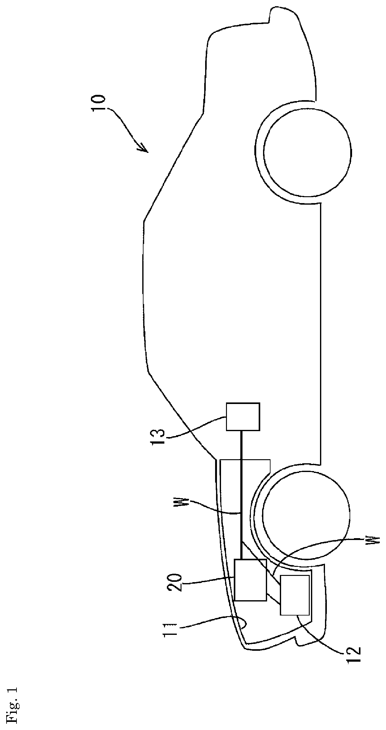
[0057]A first embodiment, which is an application of a technique disclosed in this description to a vehicle such as an automobile 10, will now be explained with reference to FIGS. 1 to 16.

[0058]As shown in FIG. 1, the automobile 10 of this embodiment includes a vehicle load 12 such as a starter motor for starting the engine or electrical equipment in an engine room 11, a battery module 20 connected to the vehicle load 12, an alternator (not shown) connected to the vehicle load 12 and the battery module 20, and a vehicle electronic control unit (ECU) 13 which controls the operation of the vehicle load 12.

[0059]The vehicle load 12 operates on electric power supplied from the battery module 20 and the alternator. When an amount of electric power supply from the alternator is small, the vehicle load 12 receives electric power supply from the battery module 20 for its operation. The alternator rotates following the operation of the engine of the automobile 10 to generate electricity and ...

second embodiment

[0126]A second embodiment will now be explained with reference to FIGS. 17 and 18.

[0127]Different from the first embodiment, a voltage-reference SOC region is determined based on a voltage and a current of the secondary batteries 30 being charged or discharged in the process for determining an SOC in the second embodiment. The explanation of the structures, operations, and advantages equal to those in the first embodiment will be omitted for avoiding redundancy. The structures equal to those in the first embodiment will be provided with the same reference signs.

[0128]The secondary batteries 30 also have a C-V correlation between a charging voltage V1 and a residual capacity RC and a C-V correlation between a discharging voltage V2 and a residual capacity RC as shown in FIGS. 17 and 18 other than the correlation between an open circuit voltage (OCV) and a state of charge (SOC) as described in the first embodiment. The residual capacity RC is an amount of electricity which can be disc...


PUM

PropertyMeasurementUnit
cell voltageaaaaaaaaaa

Abstract

The present invention is to improve the estimation accuracy of an SOC of a storage element. A storage element management device disclosed in the present description is a battery management device 50 that determines an SOC range indicating a state-of-charge of a secondary battery 30, and has a constitution including a central processing unit 61 that sets an overlapping range between an SOC range (i) R1, determined by a current integration method, and an SOC range (v) R2, determined by a voltage reference method in a stage where the SOC range (i) R1 is determined by the current integration method, as a new SOC range R3.

Description

CROSS REFERENCE TO RELATED APPLICATIONS[0001]This application is a national stage application, filed under 35 U.S.C. § 371, of International Application No. PCT / JP2017 / 000907, filed Jan. 13, 2017, which claims priority to Japanese Application No. 2016-006353, filed Jan. 15, 2016, the contents of both of which as are hereby incorporated by reference in their entirety.BACKGROUNDTechnical Field[0002]The techniques disclosed in this description relate to an energy storage device management apparatus, an energy storage device module, a vehicle, and an energy storage device management method.Description of Related Art[0003]Among the methods for estimating a state of charge (SOC) of an energy storage device of a secondary battery such as a lithium ion secondary battery, there are an OCV method in which an SOC is determined based on a correlation between an open circuit voltage (OCV) and an SOC of a secondary battery, and a current integration method in which an SOC is determined by integra...

Claims


Application Information

Patent Timeline
Patent Type & Authority Patents(United States)
IPC IPC(8): G01R31/30H02J7/00B60L50/64B60L50/60H01M10/44H01M10/42G01R31/3832G01R31/3835G01R31/3842B60L50/00H01M10/48
CPCH01M10/441B60L50/64H01M10/48B60L50/66H01M10/482G01R31/3832H02J7/0047H01M10/425G01R31/3835G01R31/3842H01M2010/4278H01M2010/4271H02J7/0048H01M2220/20Y02T10/70Y02E60/10H02J7/0013
Inventor SEJIMA, KENICHI
Owner GS YUASA INT LTD
Why Eureka
Try Eureka