Motion capturing system and method based on CAN bus and inertial sensor

A CAN bus and inertial sensing technology, applied in the input/output process of instruments, data processing, input/output of user/computer interaction, etc., can solve the problem that the size and weight are not easy to reduce, and the connection of data gathering nodes increase, the entire system cannot be used, etc., to achieve the effect of fast attitude calculation speed, simple connection, and reliable data transmission rate

Active Publication Date: 2015-11-18
JINAN ZHONGJING ELECTRONICS TECH
View PDF10 Cites 35 Cited by
  • Summary
  • Abstract
  • Description
  • Claims
  • Application Information

AI Technical Summary

Problems solved by technology

[0006] (1) Using the wireless solution, each inertial sensing node must be equipped with a lithium battery for power supply alone. When a single node or several nodes are insufficient to work, the entire system becomes unusable
[0007] (2) In the motion capture system using the SPI scheme, each inertial sensor node must be connected to a chip selection signal line, which will directly lead to the increase of the number of inertial sensor nodes, and the connection of the data sink node connected to the motion capture system The number of wires increases, and the distribution of wires in the entire system is complicated;
[0008] (3) Using the wireless solution, the size and weight of each node are not easy to reduce, which will hinder the movement to a certain extent

Method used


Image

  • Motion capturing system and method based on CAN bus and inertial sensor
  • Motion capturing system and method based on CAN bus and inertial sensor
  • Motion capturing system and method based on CAN bus and inertial sensor

Examples


Embodiment 1

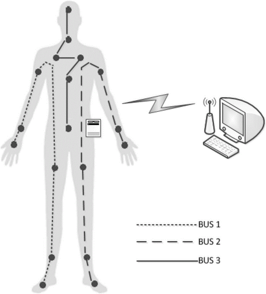
[0050] like figure 1 As shown, a motion capture system based on CAN bus and inertial sensors is composed of 18 inertial sensor nodes, data aggregation nodes and a central computer. The 18 inertial sensing nodes are respectively placed in such as figure 1 At the said marked bone point, the data gathering node is placed at the waist of the human body. The data aggregation node sends the data to the central computer through the wireless wifi module by collecting the attitude-resolved data of the 18 inertial sensor nodes.

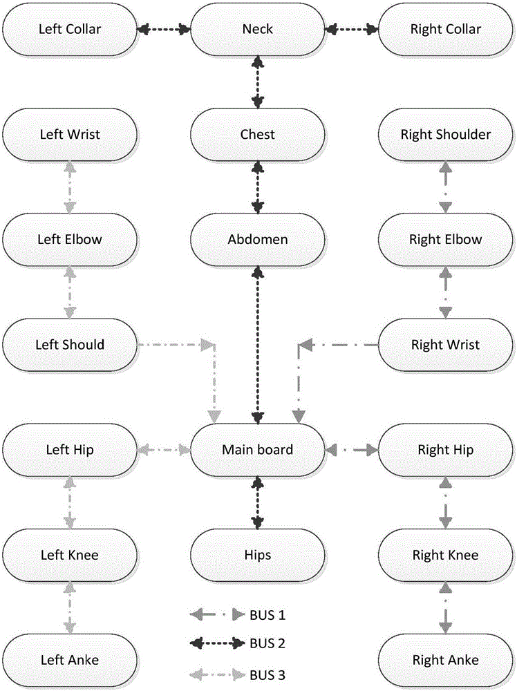
[0051] like figure 2 As shown, the 18 inertial sensor nodes are divided into 3 groups, each group contains 6 nodes, which belong to Bus1, Bus2 and Bus3 respectively. Among them, Bus1, Bus2 and Bus3 are also divided into two sections: the upper section and the lower section. This design can make the overall connection of the system the least and the wiring is convenient and simple. 18 inertial sensing nodes are placed on the user's head, left palm, left low...

Embodiment 2

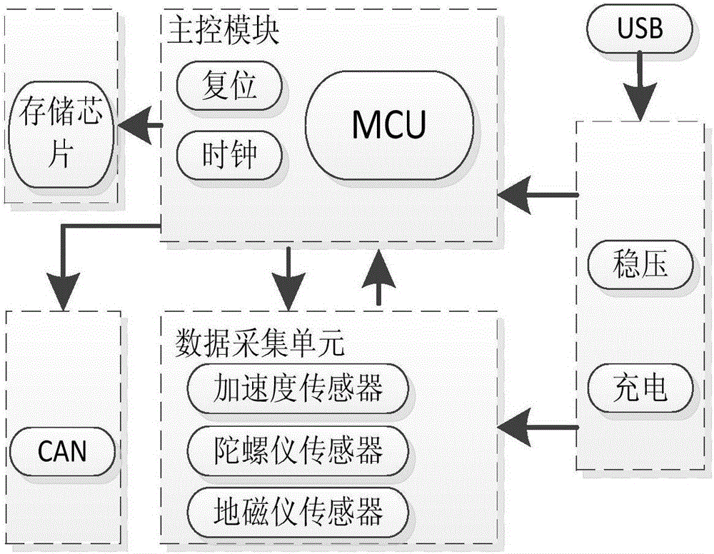
[0055] A motion capture system based on a CAN bus and an inertial sensor includes an inertial sensor node group, a data aggregation node and a central computer. The main task of the inertial sensor node group is to complete the data acquisition, filtering and attitude calculation of the three-axis acceleration, three-axis gyroscope and three-axis geomagnetism sensor of the nine-axis inertial sensor node. Quaternion or Euler angle description of spatial attitude information. The obtained quaternion or Euler angle data is converged to the data sink node in the form of CAN bus, and the data is encapsulated into a motion data frame and sent to the central computer through the wireless wifi module. The central computer first begins to create a virtual 3D character, and the initialization action is consistent with the human body action. After receiving the motion data frame, the real-time animation demonstrates the user's real-time action.

[0056] The working steps of the motion c...


PUM


Abstract

The present invention provides a motion capturing system and method based on a CAN bus and an inertial sensor, for tracking and capturing motion information of a human body in a real-time manner. The system comprises an inertial sensing node combination, a data aggregation node, and a central computer. The inertial sensing node combination contains 18 inertial sensing nodes, collects an accelerated speed, an angular speed, and geomagnetic information data of each bone point part in a real-time manner, and performs attitude estimation by using a complementary integration filtering algorithm, so as to obtain data, such as a quaternion and an euler angle, of an three-dimensional attitude of the current bone point. The data aggregation node is connected to the 18 inertial sensing nodes, is configured to collect, in a time-sharing manner, three-dimensional attitude data of each bone point obtained by the 18 inertial sensing nodes, and send the collected data to the central computer by using a wireless wifi module. A main task of the central computer is to complete functions of collecting motion data transmitted from the data aggregation node and driving a virtual 3D person model by using the motion data.

Description

technical field [0001] The invention relates to the fields of human kinematics, sensor technology, health care and the like, and in particular to a motion capture system based on CAN bus and inertial sensors. Background technique [0002] Motion capture technology is a new type of human-computer interaction technology, which has broad application prospects in rehabilitation medicine, film and television, animation, games and other fields. Using human motion capture technology, in rehabilitation medicine, it can assist patients who have lost their limbs or other specific body parts due to disease or traffic accidents to perform rehabilitation treatment; in addition, motion capture technology can also be applied to film and television production, which can simplify movies. The difficulty of production improves the fidelity of film and television characters. For example, the virtual characters in the movie "Avatar" are made using motion capture technology. The application of m...

Claims


Application Information

Patent Timeline
Patent Type & Authority Applications(China)
IPC IPC(8): G06F3/01G06F3/0346
Inventor 陈东义
Owner JINAN ZHONGJING ELECTRONICS TECH
Why Eureka
Try Eureka