Head-mounted image display device

a display device and head-mounted technology, applied in the field of head-mounted image display devices, can solve the problems of eyeglass frame unsteadiness, eyeglass frame cannot be stably attached to the head, contact section cannot be appropriately set in contact with the temporal region and the back of the head, etc., to achieve the effect of improving the universality and stably wearing of the head-mounted image display devi

Active Publication Date: 2018-02-22
SEIKO EPSON CORP
View PDF3 Cites 12 Cited by
  • Summary
  • Abstract
  • Description
  • Claims
  • Application Information

AI Technical Summary

Benefits of technology

[0010]Consequently, since the entire target contact section is movable in the left-right direction in a range of the first position to the second position, it is possible to move the entire target contact section to a position corresponding to a size of the head of the user, that is, a position where the target contact section is in contact with the temporal region. For this reason, it is possible to prevent a contact area between the head and the target contact section from changing depending on the size of the head and maintain the contact area substantially constant. Therefore, it is possible to surely set the left contact section and the right contact section respectively in contact with the left and right temporal regions and stably mount the head-mounted image display device on the head.
[0061]A dimension in the left-right direction of the head of a child (a child in a target age of the head-mounted image display device) is approximately 128 mm. A dimension in the left-right direction in the head of an adult having a relatively large head is approximately 170 mm. For this reason, with the configuration, it is possible to allow a wide variety of users ranging from children to adults to stably wear the head-mounted image display device. Therefore, it is possible to further improve universality of the head-mounted image display device.

Problems solved by technology

Therefore, it is likely that the eyeglass frame is unsteady.
However, when the user having the relatively small head uses the eyeglasses for image viewing, since the contact area between the head and the temples is small, it is likely that the eyeglass frame cannot be stably attached to the head.
Therefore, there is the same problem as explained above.
Consequently, when the left and right contact sections have shapes that are in contact with the temporal regions to the back of the head, in a configuration in which the entire target contact section is moved only in the left-right direction, although the target contact section can be set in contact with the temporal region, it is likely that the contact section cannot be appropriately set in contact with the temporal region and the back of the head.
For example, when the left and right contact sections are suspended on the ears of the user, in the configuration in which the entire target contact section is moved only in the left-right direction, it is likely that the left and right contact sections cannot be appropriately suspended on the ear.
Note that such a cover is considered to be relatively easily deteriorated because the cover is in contact with the head.
When the cover is deteriorated in this way, it is likely that a wearing feeling of the head-mounted image display device is spoiled.
Therefore, it is unnecessary to reinforce the fixing position and the fixing structure.
In such a case, the head-mounted image display device easily slants and the wearing feeling is deteriorated.

Method used


Image

  • Head-mounted image display device
  • Head-mounted image display device
  • Head-mounted image display device

Examples


first embodiment

[0108]A first embodiment of the invention is explained below with reference to the drawings.

Schematic Configuration of an HMD

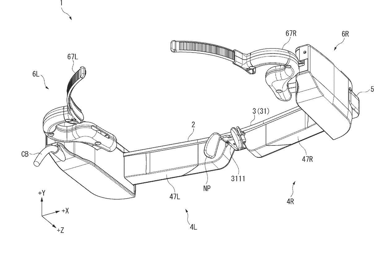
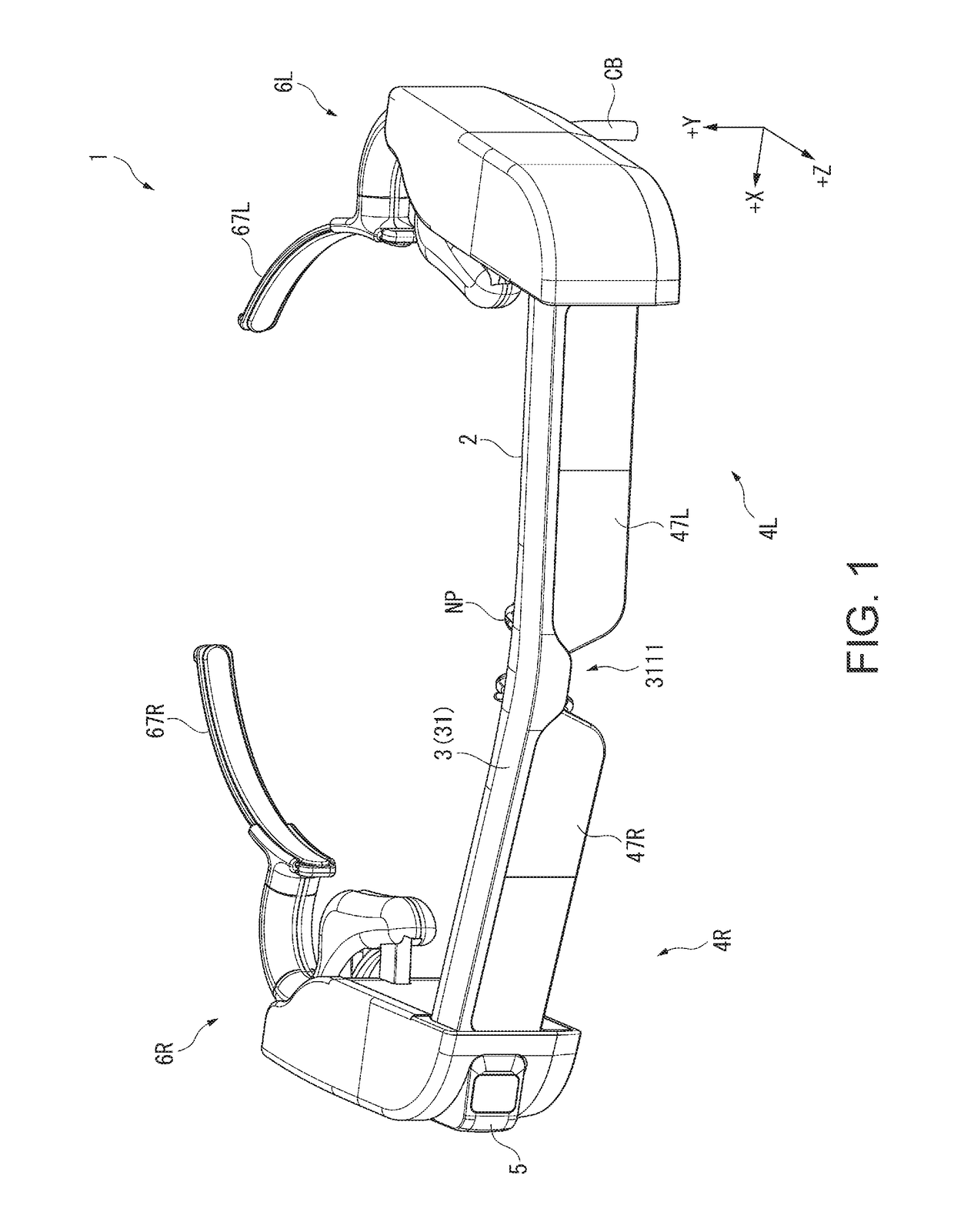
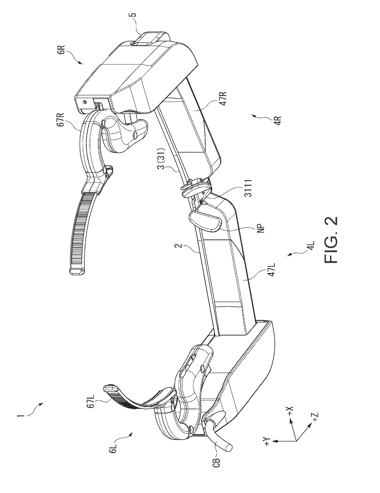
[0109]FIGS. 1 and 2 are perspective views showing the exterior of an HMD 1 according to this embodiment. Specifically, FIG. 1 is a perspective view of the HMD 1 viewed from above on the front side. FIG. 2 is a perspective view of the HMD 1 viewed from below on the back side.

[0110]The HMD 1 according to this embodiment is a head-mounted image display device of a see-through type that is mounted on the head of a user and used, displays an image to enable the user to visually recognize the image, and transmits external light to enable the user to observe an external world. The HMD 1 is a virtual image display device. The HMD 1 includes, as shown in FIGS. 1 and 2, an image display section 2 and a pair of temples 6L and 6R.

[0111]FIG. 3 is a plan view of the HMD 1 viewed from above in a state in which a dimension L1 between temples 6L and 6R (contact sections 67L an...

second embodiment

[0240]A second embodiment of the invention is explained.

[0241]An HMD according to this embodiment includes the same components and functions as the HMD 1. However, the configuration of temples is different. Note that, in the following explanation, the same or substantially same portions as the portions explained above are denoted by the same reference numerals and signs and explanation of the portions is omitted.

[0242]FIGS. 21 to 24 are diagrams showing the exterior of an HMD 1A according to this embodiment. Specifically, FIGS. 21 and 22 are respectively perspective views of the HMD 1A viewed from above on the front side and below on the back side. FIG. 23 is a plan view of the HMD 1A viewed from above in a state in which a dimension L2 between a left temple 72L and a right temple 72R is reduced most. FIG. 24 is a plan view of the HMD 1A viewed from above in a state in which the dimension L2 is increased most.

[0243]As shown in FIGS. 21 to 24, the HMD 1A according to this embodiment ...

third embodiment

[0306]A third embodiment of the invention is explained.

[0307]An HMD according to this embodiment has the same configuration of the HMD 1A. However, the configurations of a frame and temples are different. Note that, in the following explanation, the same or substantially same portions as the portions explained above are denoted by the same reference numerals and signs and explanation of the portions is omitted.

[0308]FIGS. 31 and 32 are perspective views showing the exterior of an HMD 1B according to this embodiment. FIG. 31 is a perspective view of the HMD 1B viewed from above on the front side. FIG. 32 is a perspective view of the HMD 1B, in which a part of a temple 8 is separated, viewed from above on the back side. Note that, in FIG. 32, for convenience of illustration, first links 831 and urging sections 834 are disengaged. In FIG. 32, a blocking member SD is omitted.

[0309]As shown in FIGS. 31 and 32, the HMD 1B according to this embodiment includes the same components and funct...


PUM


Abstract

A head-mounted image display device mounted on the head of a user includes an image display section, a left contact section set in contact with a temporal region on the left side, a right contact section set in contact with a temporal region on the right side, a left supporting section provided in the image display section and configured to support the left contact section, and a right supporting section provided in the image display section and configured to support the right contact section. At least one supporting section of the left supporting section and the right supporting section supports an entire target contact section, which is the contact section supported by the at least one supporting section of the left and right contact section, to be movable from a first position to a second position away from the first position in a left-right direction with respect to the head.

Description

BACKGROUND1. Technical Field[0001]The present invention relates to a head-mounted image display device.2. Related Art[0002]There has been known a head-mounted image display device (HMD: Head Mounted Display) that is mounted on the head of a user and displays an image to enable the user to observe the image. As such a head-mounted image display device, there is known eyeglasses for image viewing including an eyeglass frame including opening sections corresponding to the left and right eyes, left and right temple holders connected to the left and the right of the eyeglass frame via hinge sections, and temples coupled to the temple holders, the width between the left and right temples being adjustable (see, for example, JP-A-2011-85929 (Patent Literature 1)).[0003]In the eyeglasses for image viewing described in Patent Literature 1, columnar turning members are fastened to the temple holders by screws via leaf springs. The turning members are configured to be turnable around the center...

Claims


Application Information

Patent Timeline
Patent Type & Authority Applications(United States)
IPC IPC(8): G02B27/01G02B27/22
CPCG02B27/0172G02B27/0103G02B2027/0178G02B2027/012G02B27/2264G02B2027/0159G02B2027/0181G02B27/0176G02B30/24
Inventor KAMAKURA, KAZUYA
Owner SEIKO EPSON CORP
Why Eureka
Try Eureka