

Bipolar battery
a battery and bipolar technology, applied in the field of bipolar batteries, can solve the problems of difficult to prevent and achieve the effect of suppressing the exhaustion suppressing the leakage of the electrolytic solution
- Summary
- Abstract
- Description
- Claims
- Application Information
AI Technical Summary
Benefits of technology
Problems solved by technology
Method used
Image

Examples
embodiment 1
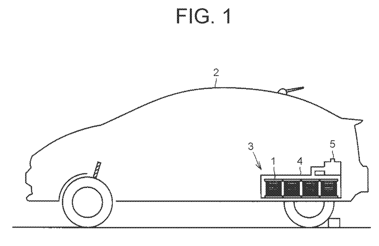
[0054]With reference to FIG. 1 to FIG. 22, a bipolar battery according to each embodiment will be described. In FIG. 1 to FIG. 22, the same or substantially the same configurations will be denoted with the same reference numerals, and overlapped description thereof might be omitted. FIG. 1 is a schematic view schematically showing a vehicle 2 in which bipolar batteries 1 according to the present embodiment 1 are installed. As shown in FIG. 1, the vehicle 2 includes a battery unit 3.
[0055]The battery unit 3 includes a battery case 4 housing the multiple bipolar batteries 1 therein, and a fan 5 supplying a cooling air into the battery case 4.
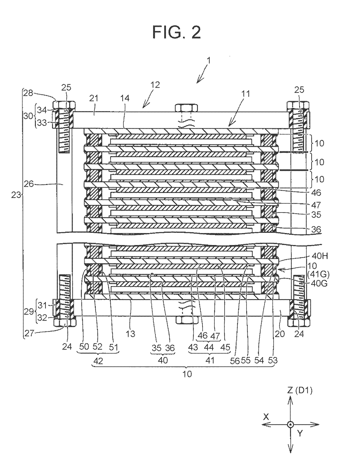
[0056]FIG. 2 is a cross sectional view showing the bipolar battery 1, and FIG. 3 is an exploded perspective view of the bipolar battery 1. As shown in FIG. 2, the bipolar battery 1 includes a stacked body 11 formed by stacking multiple unit cells 10 in a stacking direction D1, and a fastening tool 12 to fasten the stacked body 11 in the stacking d...
embodiment 2
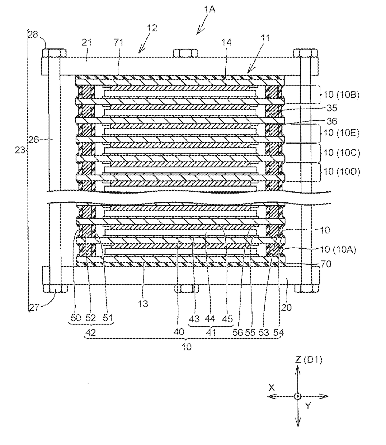
[0094]Further, the fastening tool 12 does not close the stacked body 11, so that circumferential surfaces of the stacked body 11 are exposed to the outside air, and the stacked body 11 can be directly cooled by cooling air or the like. In the present embodiment 2, there will be described a configuration to provide heat insulating members between the stacked body and the pressing plates so as to reduce variation in temperature of the unit batteries at the uppermost position and the lowermost position, to thereby stabilize electric characteristics of the bipolar battery.
[0095]FIG. 6 is a cross sectional view showing a bipolar battery 1A according to the embodiment 2. As shown in FIG. 6, the bipolar battery 1A includes the stacked body 11, a heat insulating member 70 disposed between the stacked body 11 and the pressing plate 20, and a heat insulating member 71 disposed between the stacked body 11 and the pressing plate 21.
[0096]The stacked body 11 includes: a unit cell 10A adjacent to...
embodiment 3
[0106]In the above example, the case in which both the heat insulating members 70, 71 are provided has been explained, but one of the heat insulating members 70, 71 may be provided. In this case, the electric insulating member 29 or the electric insulating member 30 is provided. In the present embodiment 3, there will be described a configuration that for the sake of promoting enhancement of the heat dissipation of the stacked body 11, each of the current collecting plates 40 is formed with a heat-dissipating portion greatly protruding from the seal member 42, to thereby promote enhancement of the heat dissipation of the stacked body 11.
[0107]FIG. 8 is a cross sectional view showing a bipolar battery 1C according to the embodiment 3. As shown in FIG. 8, the outer circumferential edge of each current collecting plate 40 is so formed as to protrude more outward than each seal member 42. Of each current collecting plate 40, a portion protruding more outward than the seal member 42 is r...
PUM
| Property | Measurement | Unit |
|---|---|---|
| thickness | aaaaa | aaaaa |
| mass % | aaaaa | aaaaa |
| contact angle | aaaaa | aaaaa |
Abstract
Description
Claims
Application Information