

Engine starting system
a technology for engine starting and engine, applied in the direction of engine starters, electric motor starters, machines/engines, etc., can solve the problems of deteriorating engine startability, adversely affecting the startability of the engine, so as to achieve optimal engine start-up
- Summary
- Abstract
- Description
- Claims
- Application Information
AI Technical Summary
Benefits of technology
Problems solved by technology
Method used
Image

Examples
first embodiment
Modification of First Embodiment
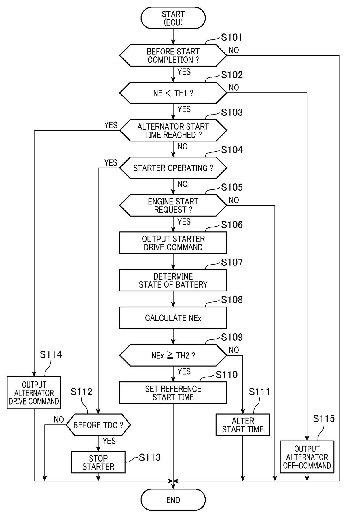
[0097]The engine starting system of the first embodiment is designed to output the drive command to the starter 11 when it is required to start the engine 10, monitor the state parameter of the battery 31 to calculate the engine speed NEx that is the speed of the engine 10 expected in this engine cranking cycle, and determine the start time of the alternator 20 as a function of the engine speed NEx (see steps S107 to S111 in FIG. 3), but however, may alternatively be engineered to determine a peak value of the speed of the engine 10 (i.e., the cranking speed) when the starter 11 is operating and calculate the start time of the alternator 20 as a function of the peak value.
[0098]The above structure will be described in detail with reference to a flowchart of FIG. 8. The flowchart of FIG. 8 is a sequence of logical steps executed by the ECU 30 in a cycle instead of that in FIG. 3. The same step numbers as employed in FIG. 3 refer to the same operations,...
second embodiment
[0108]The engine starting system of the second embodiment will be described below. The engine starting system of the first embodiment determines the start time of the alternator 20 using a parameter correlating with the operational condition of the starter 11, while the engine starting system of the second embodiment works to determine a stop time that is a target time at which the starter 11 should be stopped, i.e., turned off using a parameter correlating with the operational condition of the alternator 20.
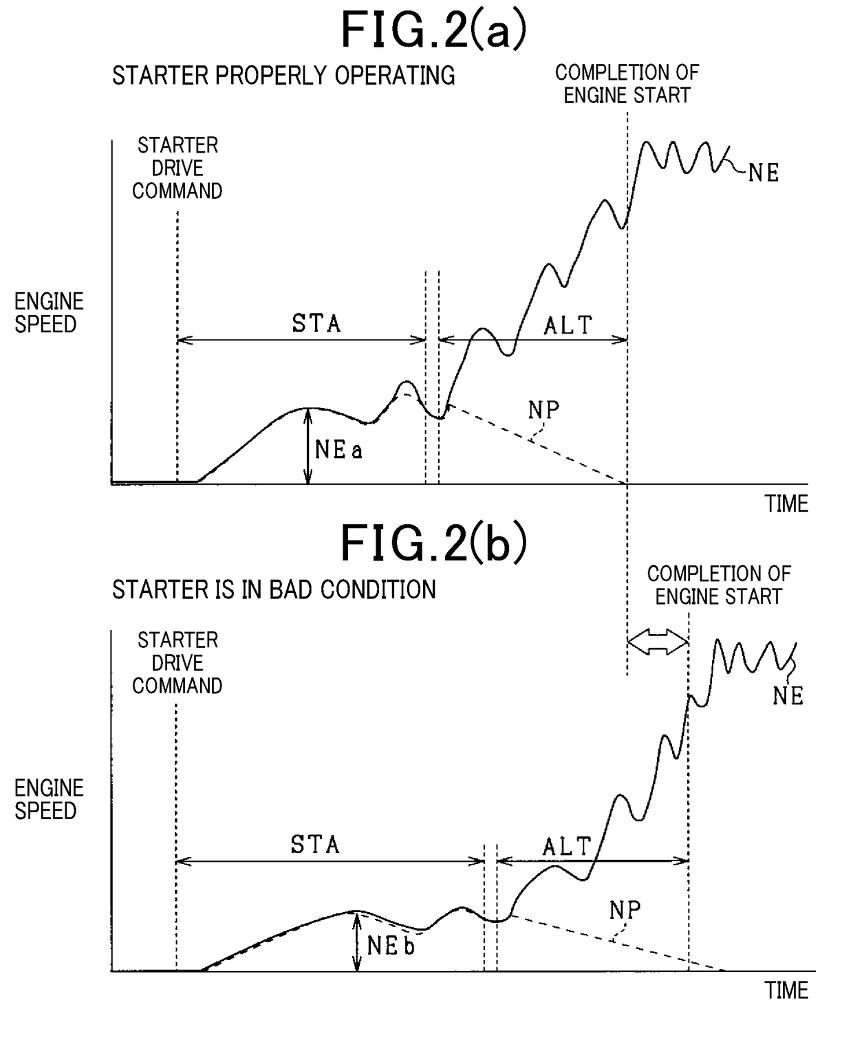
[0109]At the starting stage of the engine 10 using the starter 11 and the alternator 20, the operating condition of the starter 11 may be changed by various factors. For instance, when the starter 11 is not capable of properly operating, as demonstrated in FIG. 2(b), it will result in an insufficient increase in speed of the engine 10. In such an event, the start time when the alternator 20 is actuated in the motor mode may be delayed.
[0110]More specifically, the engine starting...
third embodiment
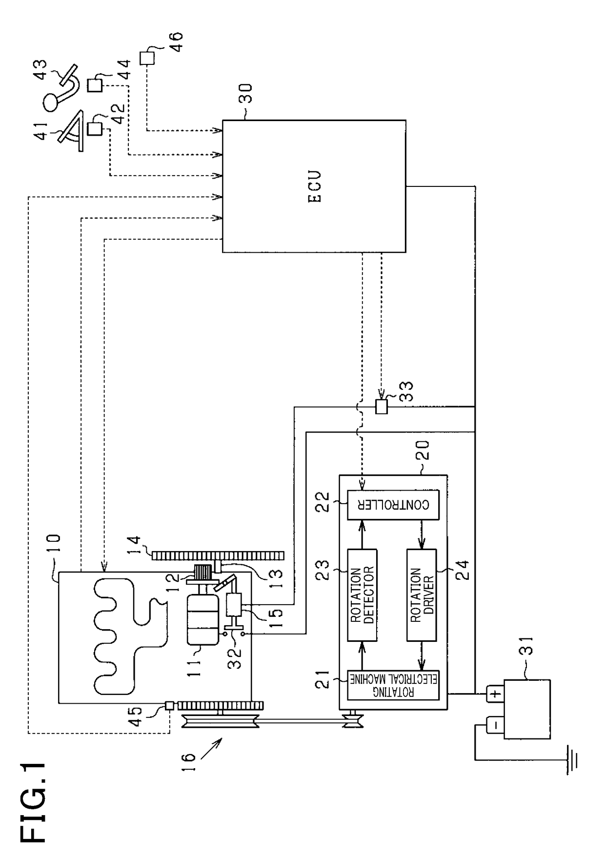
[0133]The engine starting system of the third embodiment will be described below. The engine starting system of the first embodiment has the battery 31 to which the starter 11 and the alternator 20 are electrically connected and supplies electrical power both to the starter 11 and to the alternator 20 from the battery 31, while the engine starting system of the third embodiment has separate batteries which deliver electrical power to the starter 11 and the alternator 20, respectively.
[0134]FIG. 13 schematically illustrates the structure of the engine starting system of the third embodiment. The battery 34 is electrically joined to the starter 11 and serves as a first power supply which delivers electrical power to actuate the starter 11. The battery 35 is electrically connected to the alternator 20 and serves as a second power supply which delivers electrical power to actuate the alternator 20. Specifically, when it is required to operate the alternator 20 as an electrical motor, th...
PUM
 Abstract
Description
Claims
Application Information