
Self-piercing rivet, arrangement with a self-piercing rivet, and method for forming a joint in a stack of at least two sheets of material

Inactive Publication Date: 2018-03-01
NEWFREY
View PDF8 Cites 2 Cited by
  • Summary
  • Abstract
  • Description
  • Claims
  • Application Information

AI Technical Summary

Benefits of technology

The patent text describes a method for joining sheets of metal using a special rivet called a self-piercing rivet. This rivet allows for a clean and secure joint, even with sheets made of low ductility metals like aluminum or magnesium. The rivet has a hollow space inside it, with a thin lid to prevent material from sticking out. This design also allows for a blow feed rivet delivery system. The die, which is a tool used to make the rivet, should have a volume between 70% and 120% of the volume of the rivet. This can be reduced without affecting the quality of the joint.

Problems solved by technology

However, even though the C rivet has proved to be successful in practice, it comes up against limiting factors in particular in the case of self-piercing riveting material with low ductility such that lightweight material.
In practice such self-piercing rivet that is fully hollow does not allow a clean, neat junction.
Besides, the delivery operation of such rivets can be difficult to implement.

Method used


Image

  • Self-piercing rivet, arrangement with a self-piercing rivet, and method for forming a joint in a stack of at least two sheets of material
  • Self-piercing rivet, arrangement with a self-piercing rivet, and method for forming a joint in a stack of at least two sheets of material
  • Self-piercing rivet, arrangement with a self-piercing rivet, and method for forming a joint in a stack of at least two sheets of material

Examples


Embodiment Construction

[0050]On the different figures, the same reference signs designate identical or similar elements.

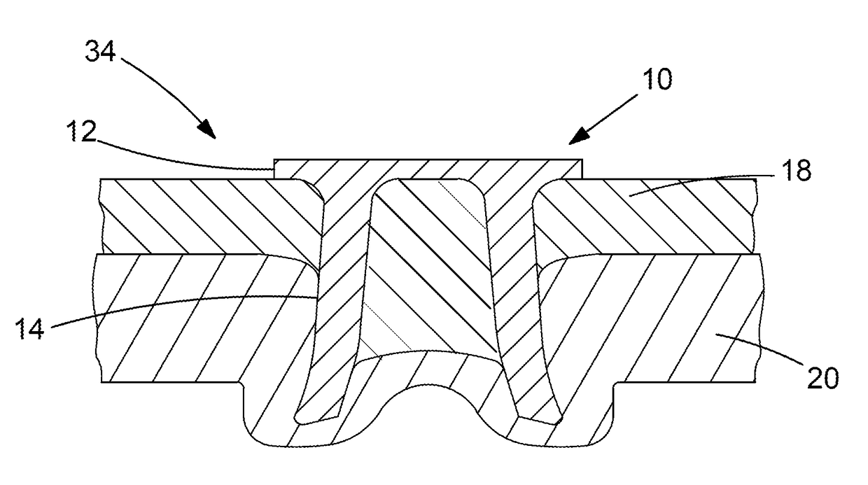
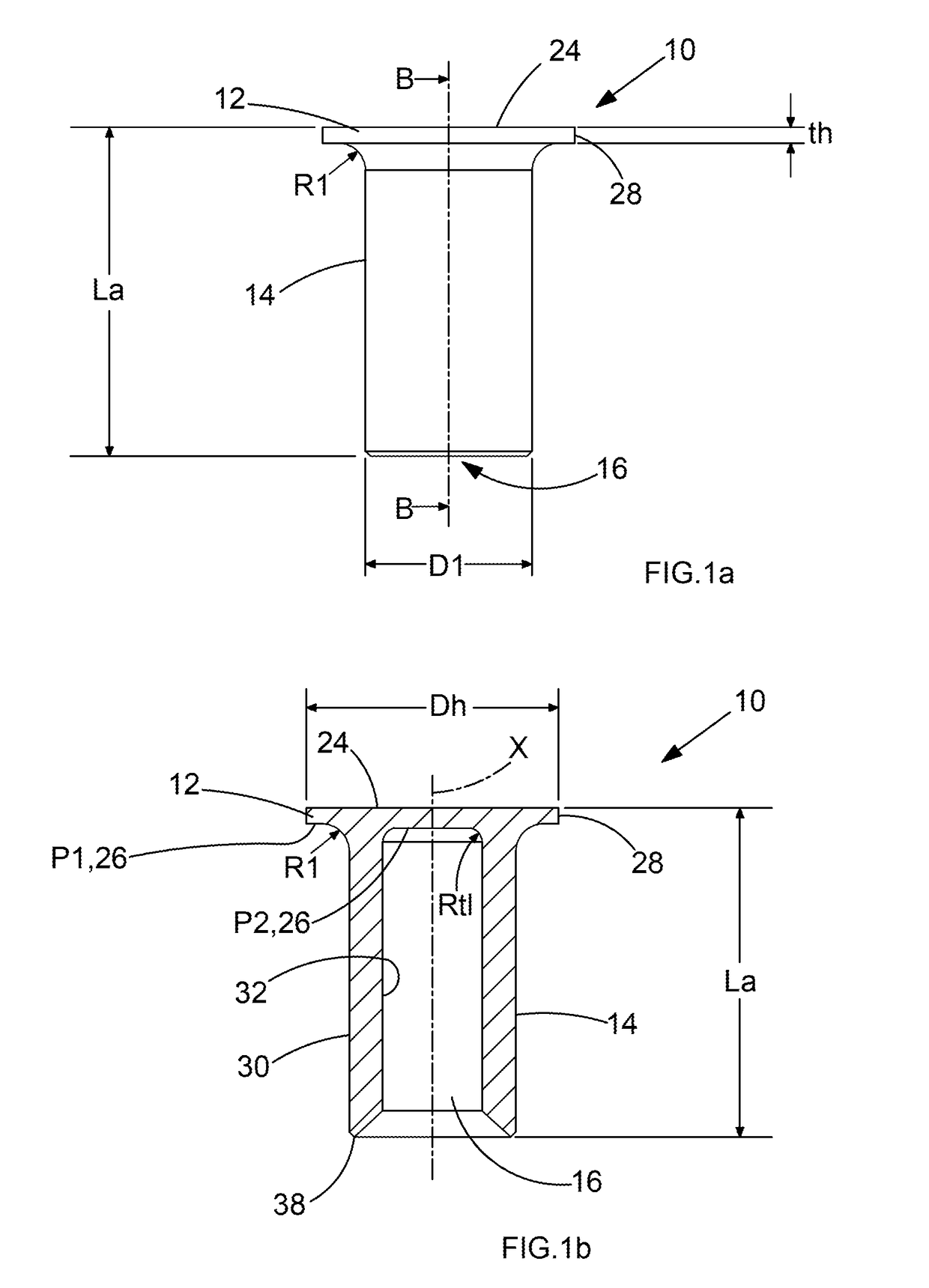
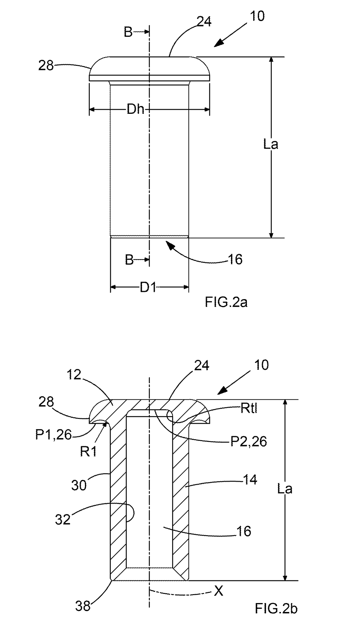
[0051]FIG. 1 and FIG. 2 show a self-piercing rivet 10 adapted to join a stack of at least two sheets 18, 20, 22 of material. The self-piercing rivet 10 comprises a rivet head 12 and a rivet shank 14. The rivet shank 14 is provided with a central shank hole 16. The rivet head 12, the rivet shank 14 and the central shank hole 16 are rotationally symmetrical with reference to a central axis X. In other words, the self-piercing rivet 10 is formed rotationally symmetrical with respect to the central axis X.

[0052]The rivet head 12 comprises a top side 24, a bottom side 26 opposite the top side 24 and a cylindrical head exterior surface 28. The rivet head 12 has a circular cross section. The cylindrical head exterior surface 28 connects the top side 24 and the bottom side 26. The cylindrical head exterior surface 28 has a predetermined head diameter Dh. The predetermined head diameter Dh of the...


PUM

PropertyMeasurementUnit
Lengthaaaaaaaaaa
Fractionaaaaaaaaaa
Fractionaaaaaaaaaa

Abstract

A self-piercing rivet for joining a stack of at least two sheets of material. The rivet comprises a rivet head rotationally symmetrical to a central axis, and the rivet head includes a top side, a bottom side opposite the top side, and a cylindrical head exterior surface of a head diameter. The rivet head has a thickness (th) along the central axis. The rivet further comprises a rivet shank rotationally symmetrical to the central axis and including a cylindrical shank exterior surface and a cylindrical shank interior surface. The shank interior surface and the bottom side of the rivet head partially define a central shank hole that is open in an axial direction opposite to the bottom side of the rivet head. The rivet has an axial length (La) along the central axis, and the ratio between the head thickness and the axial length is between 1 / 7 and 1 / 22.

Description

CROSS-REFERENCE TO RELATED APPLICATIONS[0001]This application claims priority from European Provisional Patent Application No. 16185400.5 filed Aug. 23, 2016, the disclosures of which are incorporated herein by reference in their entirety.BACKGROUND OF THE INVENTION[0002]The present invention relates to a self-piercing rivet for joining a stack of at least two sheets of material, to an arrangement with a self-piercing rivet and a stack of sheets and to a method for forming a joint with such a self-piercing rivet whereby the rivet is inserted into sheet material without full penetration such that a deformed end of the rivet remains encapsulated by an upset annulus of the sheet material.[0003]More particularly, the present invention relates to a self-piercing rivet in the form of a “semi-hollow” self-piercing rivet.[0004]EP 0 720 695 discloses such a semi-hollow rivet, which is normally described as a C rivet. This type of rivet is used on a large scale in the motor vehicle industry, ...

Claims


Application Information

Patent Timeline
IPC IPC(8): F16B19/08F16B5/04B21J15/02
CPCF16B19/086B21J15/025F16B5/04B21J15/36
Inventor WISSLING, MATTHIASBARTIG, PAUL
Owner NEWFREY
Learn More