Load monitoring system

a monitoring system and load technology, applied in the direction of lifting devices, lifting equipment safety devices, weighing apparatuses, etc., can solve the problems of annoyance for operators, and achieve the effect of reducing at least some of the disadvantages

Active Publication Date: 2013-11-19
NIFTYELEVATOR
View PDF15 Cites 5 Cited by
  • Summary
  • Abstract
  • Description
  • Claims
  • Application Information

AI Technical Summary

Benefits of technology

[0007]It is an object of the present invention to provide a mobile work platform and a load monitoring system for a mobile work platform that mitigate at least some of the aforesaid disadvantages.

Problems solved by technology

The system does not therefore suffer from “nuisance tripping”, which can be very annoying for the operator.

Method used


Image

  • Load monitoring system
  • Load monitoring system
  • Load monitoring system

Examples


Embodiment Construction

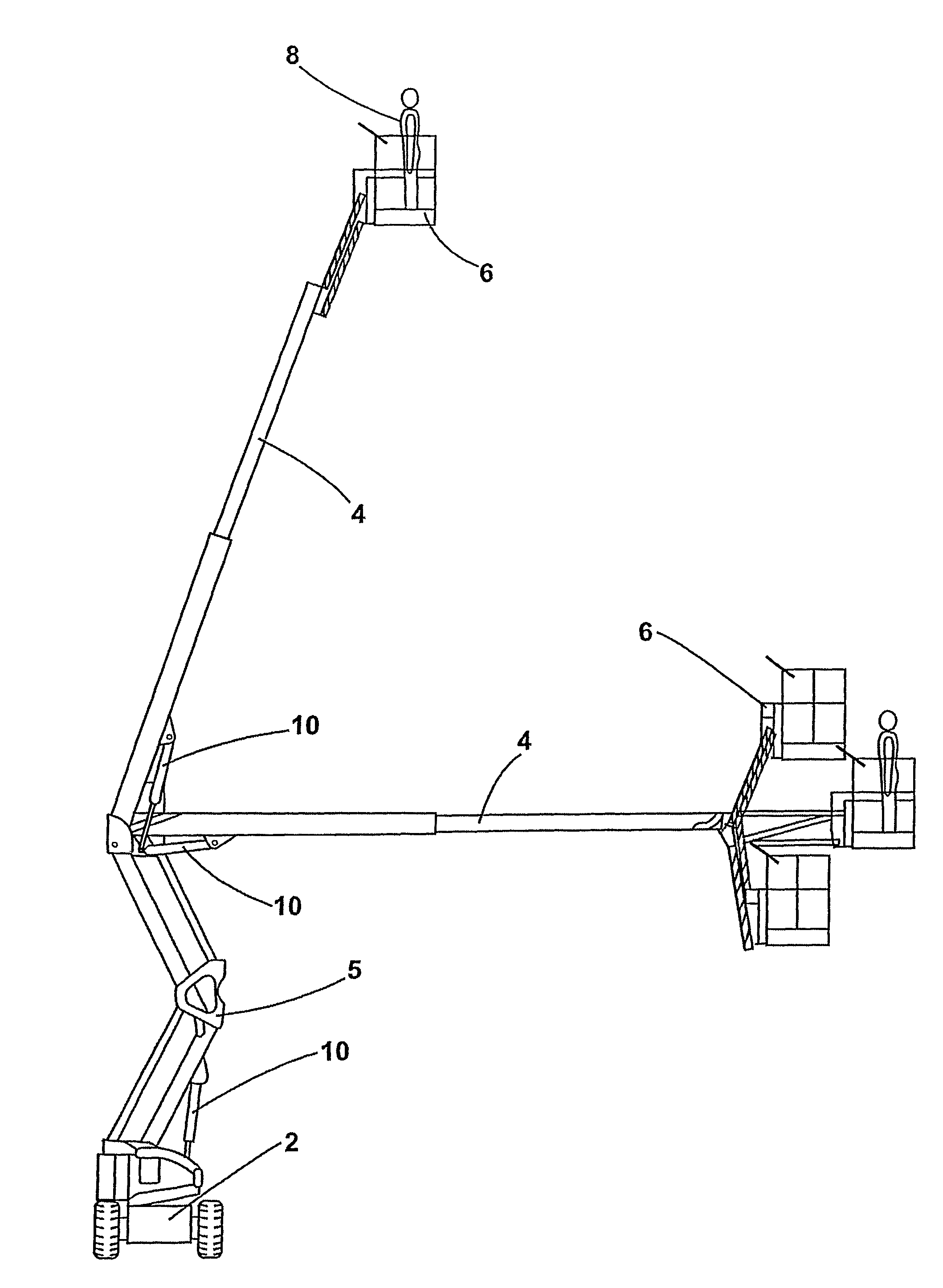
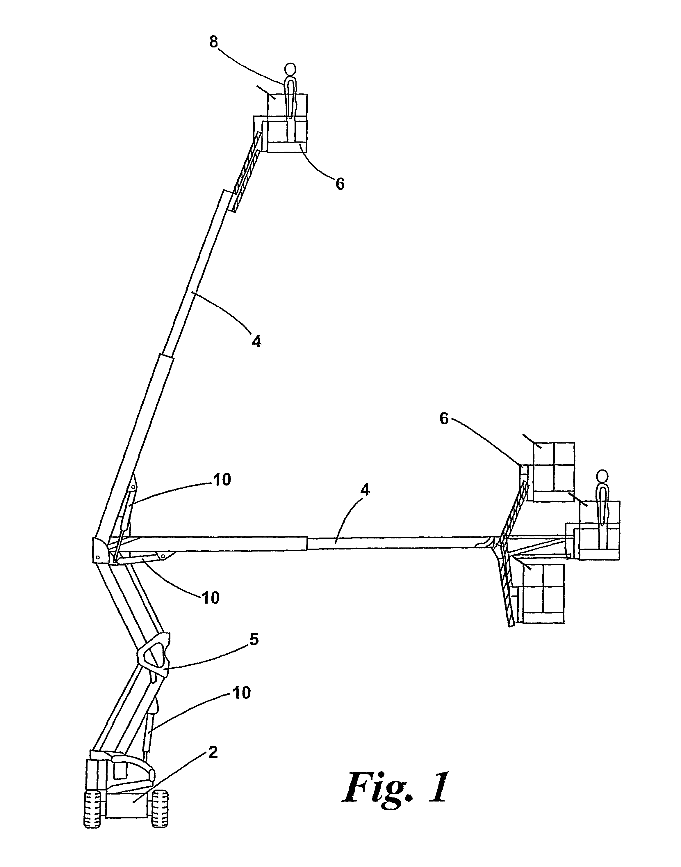
[0021]FIG. 1 shows a typical mobile work platform according to an embodiment of the invention, which includes a wheeled base unit 2, a hydraulically operated lift mechanism comprising a boom 4 and a lifting structure 5, and an operator platform (or cage) 6 for a human operator 8. The boom 4, which is shown here in various operating configurations, may be retracted and folded onto the base unit 2 for transportation or storage. Movement of the boom 4 is controlled by hydraulic cylinders 10, which are connected by hydraulic hoses (not shown) to a hydraulic drive system. Hydraulic motors may also be provided for driving the wheels. The components shown in FIG. 1 are all conventional and will not therefore be described in detail. It should be understood that the mobile work platform may take various alternative forms.

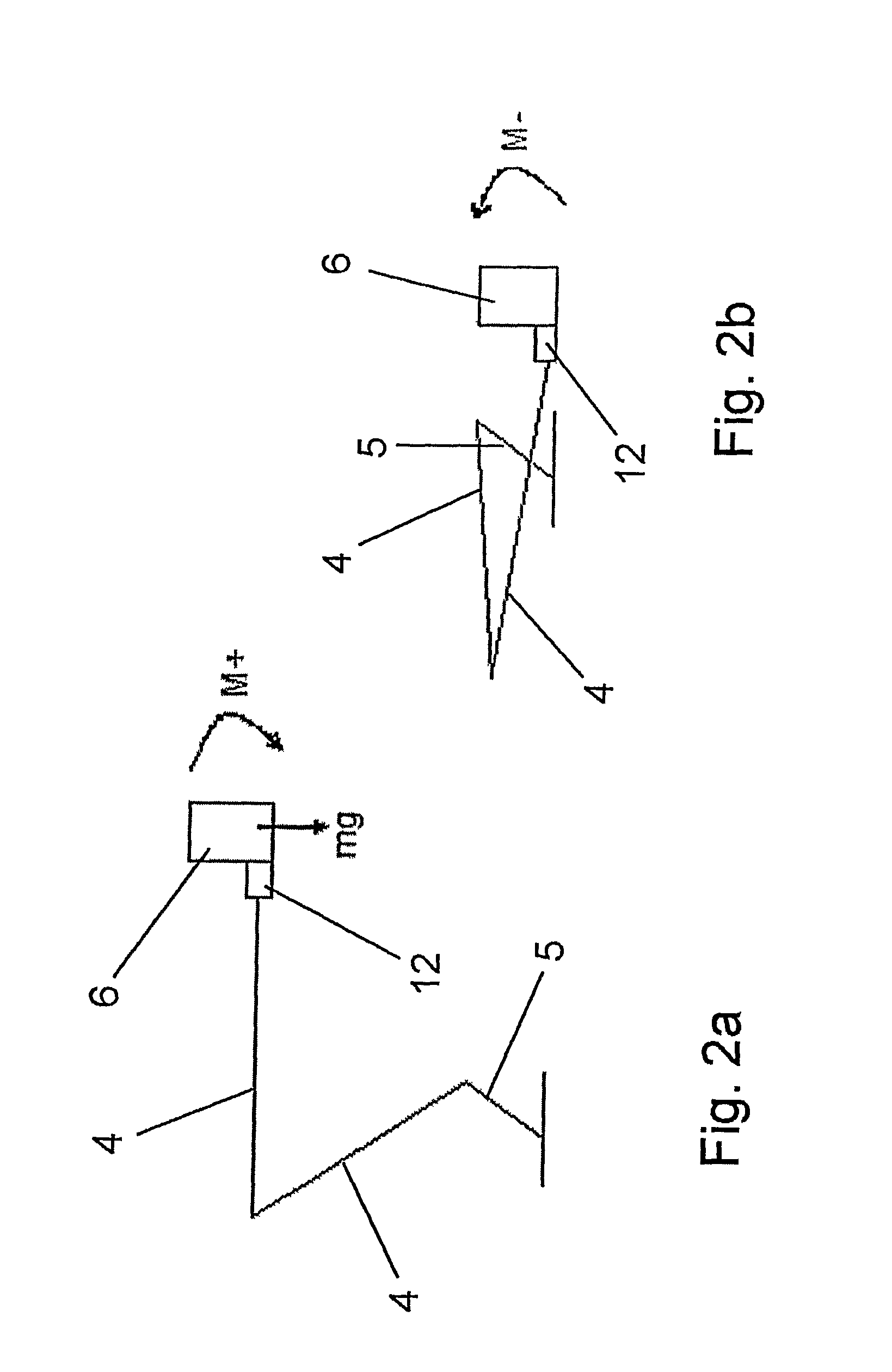
[0022]As shown schematically in FIGS. 2a and 2b, the cage 6 is connected to the boom 4 via a load cell 12. The load cell 12 is conventional in design and comprises an alumin...


PUM


Abstract

A load monitoring system (14) is provided for a mobile work platform that includes an operator platform (6), a base (2) and a lift mechanism (5) for lifting the operator platform relative to the base. The load monitoring system includes a load cell (12) for monitoring the load on the operator platform (6) and a control device (16) for controlling operation of the work platform, wherein the control device (16) is constructed and arranged to sense and monitor both static and dynamic loads on the operator platform.

Description

RELATED APPLICATIONS[0001]The instant application is the U.S. National Phase under 35 U.S.C. §371 of International Application No. PCT / GB2009 / 002143 entitled LOAD MONITORING SYSTEM, filed Sep. 8, 2009, designating the U.S., which claims priority under 35 U.S.C §119(a)-(d) to Great Britain Patent Application No. 0817845.1, filed Sep. 30, 2008. The content of these applications is herein incorporated by reference in its entirety.FIELD OF THE INVENTION[0002]The present invention relates to a load monitoring system for a work platform and to a work platform having a load monitoring system. In particular but not exclusively the invention relates to mobile work platforms and load monitoring systems therefor.BACKGROUND OF THE INVENTION[0003]Mobile work platforms typically include a cage or platform that is designed to receive one or more human operators. The cage is mounted on a lift mechanism, such as a hydraulic boom or a scissor lift mechanism, that allows its height to be adjusted. The...

Claims


Application Information

Patent Timeline
Patent Type & Authority Patents(United States)
IPC IPC(8): B66F11/04
CPCG01G19/083B66F11/046B66F17/006
Inventor BOWDEN, FRANK ROGER
Owner NIFTYELEVATOR
Why Eureka
Try Eureka