Overvoltage protection device comprising a disconnection accessory

Active Publication Date: 2011-01-20
ABB FRANCE SAS
View PDF6 Cites 21 Cited by
  • Summary
  • Abstract
  • Description
  • Claims
  • Application Information

AI Technical Summary

Benefits of technology

[0017]The present invention provides an overvoltage protection device which at least partially mitigates the aforesai

Problems solved by technology

Sometimes, thermal protection is based on an electronic measurement of the current, as described, for example, in FR-A-2 873 510, which has the disadvantage of being very costly.
The disadvantage is that the thermal protection and the protection against short-circuits are separate and each use a respective cut-off device.
However, the fact of using two cut-off devices has the disadvantage of both increasing the spatial requirements of the protection device and the cost thereof.
However, this device has several disadvantages.
A pin made of a thermofusible material is thus not very precise as concerns the temperature at which it melts or breaks and therefore causes the circuit breaker to be triggered.
The metal alloy pin having a low melting temperature ensures a higher degree of precision, but, besides the higher cost thereof, has the disadvantage of being very difficult to produce and generally contains lead or cad

Method used


Image

  • Overvoltage protection device comprising a disconnection accessory
  • Overvoltage protection device comprising a disconnection accessory
  • Overvoltage protection device comprising a disconnection accessory

Examples


fourth embodiment

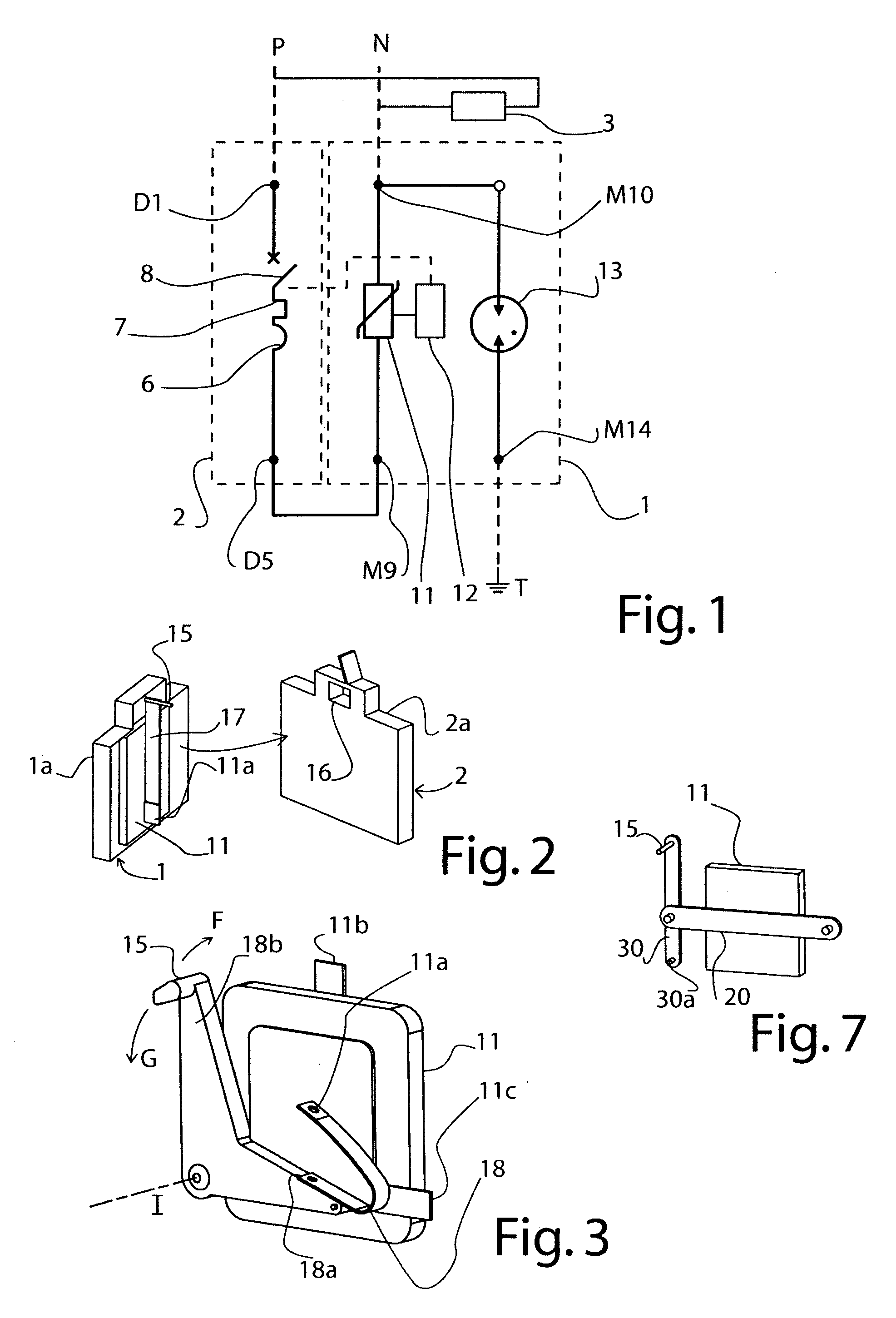
[0128]FIG. 7 shows the functional portion of a protection module according to the invention. In this case, the thermosensitive member consists of a heat-retractable bar 20. The latter can be made of any appropriate heat-retractable material, which, for example, can be chosen from amongst a polyolefin, a fluoropolymer such as PVC, FEP, PTFE, Kynar® and PVDF, and a chlorinated polyolefin such as neoprene. The heat-retractable bar 20 is attached at one end 20a in a case 1a. The actuating means 12 also include a lever 30 mounted pivotably in the case 1a, e.g., by one of the ends thereof 30a. The other end of the lever 30 bears the triggering bar 15 intended to cooperate with the triggering mechanism of the cut-off device 2. The heat-retractable bar 20 shrinks and thereby causes the lever 30 to pivot. Under the influence of an increase in its temperature beyond a given threshold, the bar 20 retracts and thereby causes the lever 30 to pivot. Correspondingly, the triggering bar 15 actuates...

fifth embodiment

[0129]FIGS. 8a and 8b show the functional portion of a protection module. In this embodiment, the thermosensitive member is a deformable capsule 40 filled with a fluid causing deformation of the capsule based on the temperature thereof. Preferably, deformation of the capsule 40, which serves to actuate the triggering mechanism of the circuit breaker, is caused by vaporization of the fluid, which obtains a substantially bistable deformation property. The capsule 40 is arranged on the principal face of the varistor 11. FIGS. 8a and 9a show the capsule 40 at ambient temperature, which corresponds to the normal operation of the device. In the event of overheating of the varistor 11, the fluid contained in the capsule 40 vaporises when reaching the latent heat of vaporisation, and the capsule 40 thus swells, as shown in FIGS. 8b and 9b. The capsule 40 then acts on a mechanism, symbolised by the reference sign 41, thereby transmitting movement to a triggering bar, which cooperates with th...


PUM


Abstract

A device for protecting against overvoltages that includes at least one overvoltage protection component (11); a thermosensitive member (17) capable of deforming, dependent upon the temperature thereof; a thermal connection between the at least one protection member and the thermosensitive member; and at least one mechanical member (15) for cooperating with the thermosensitive member and capable of cooperating with a system for triggering an electrical cut-off device (2). The thermosensitive member (17) and the at least one mechanical member (15) are arranged such that, when the thermosensitive member exceeds a given temperature threshold, the thermosensitive member, by reason of the deformation thereof, causes a movement of said at least one mechanical member (15) which correspondingly actuates the system for triggering the electrical cut-off device.

Description

CROSS-REFERENCE TO RELATED APPLICATION[0001]This is a National Phase Application filed under 35 U.S.C. 371 of International Application No. PCT / FR2008 / 001777, filed on Dec. 18, 2008, which claims priority under 35 U.S.C. §119 to French Application No. 0708820, filed on Dec. 18, 2007; the entire contents of both applications being hereby incorporated by reference.BACKGROUND OF THE INVENTION[0002]The present invention relates to the general technical field of devices for protecting electrical equipment or installations against electrical disturbances, in particular against transient overvoltages due in particular to a lightning strike. This invention relates more particularly to a protection device, such as a varistor-type surge arrester, associated with or intended to be associated with an electric cut-off device such as a circuit breaker.[0003]It is known to ensure overvoltage protection of an electrical installation by means of devices including at least one overvoltage protection ...

Claims


Application Information

Patent Timeline
IPC IPC(8): H01H73/00
CPCH01H83/10H01H2089/005H01H2083/206H01H83/20
Inventor CREVENAT, VINCENTBORIS, GAUTIER
Owner ABB FRANCE SAS
Why Eureka
Try Eureka