Method for forming a joint in a stack of light metal alloy sheets

a technology of light metal alloy sheets and stacks, applied in sheet joining, rivets, screws, etc., can solve the problems of significant risk of rivet collapse, difficult or inconvenient spot welding of aluminum, and rivets not always suitable for thick stacks, etc., to achieve the effect of reducing the disadvantages

Active Publication Date: 2016-04-19
ATLAS COPCO IAS UK LIMITED
View PDF29 Cites 12 Cited by
  • Summary
  • Abstract
  • Description
  • Claims
  • Application Information

AI Technical Summary

Benefits of technology

[0008]It is one object of the present invention to obviate or mitigate the aforesaid disadvantages. It is also an object of the present invention to provide for an improved or alternative self-piercing rivet.

Problems solved by technology

Aluminium is difficult or not feasible to spot weld, particularly to steel, owing to its high thermal conductivity, low melting range and propensity to form oxide surface film.
Since such steels have a high ultimate tensile strength the insertion forces applied to the rivet are necessarily high there is thus a significant risk of rivet collapse.
It has been established that such a rivet is not always suitable for use with thick stack, high strength light metal alloys such as magnesium and aluminium alloys especially where the material combination may have three or more layers.
Moreover, other conventional rivets are not generally suitable for joining such materials.
Aluminium alloy sheet material generally exhibits superior ductility and so dies with relatively deep cavities tend to be used but the joints suffer from the tendency for the middle sheets to push through the lowermost sheet in the insertion process.
This leaves a weakened joint which is often prone to corrosion and it may not be possible to produce a satisfactory joint repeatedly in a mass production environment.

Method used


Image

  • Method for forming a joint in a stack of light metal alloy sheets
  • Method for forming a joint in a stack of light metal alloy sheets
  • Method for forming a joint in a stack of light metal alloy sheets

Examples


Embodiment Construction

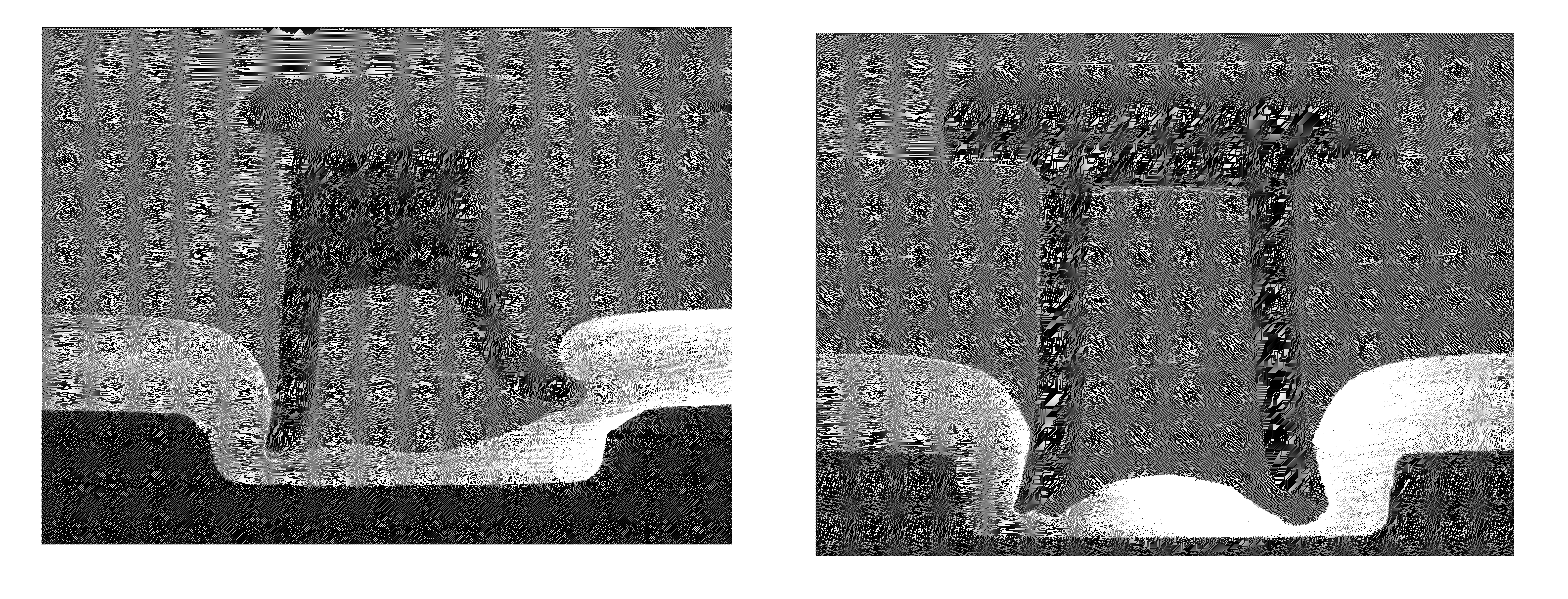
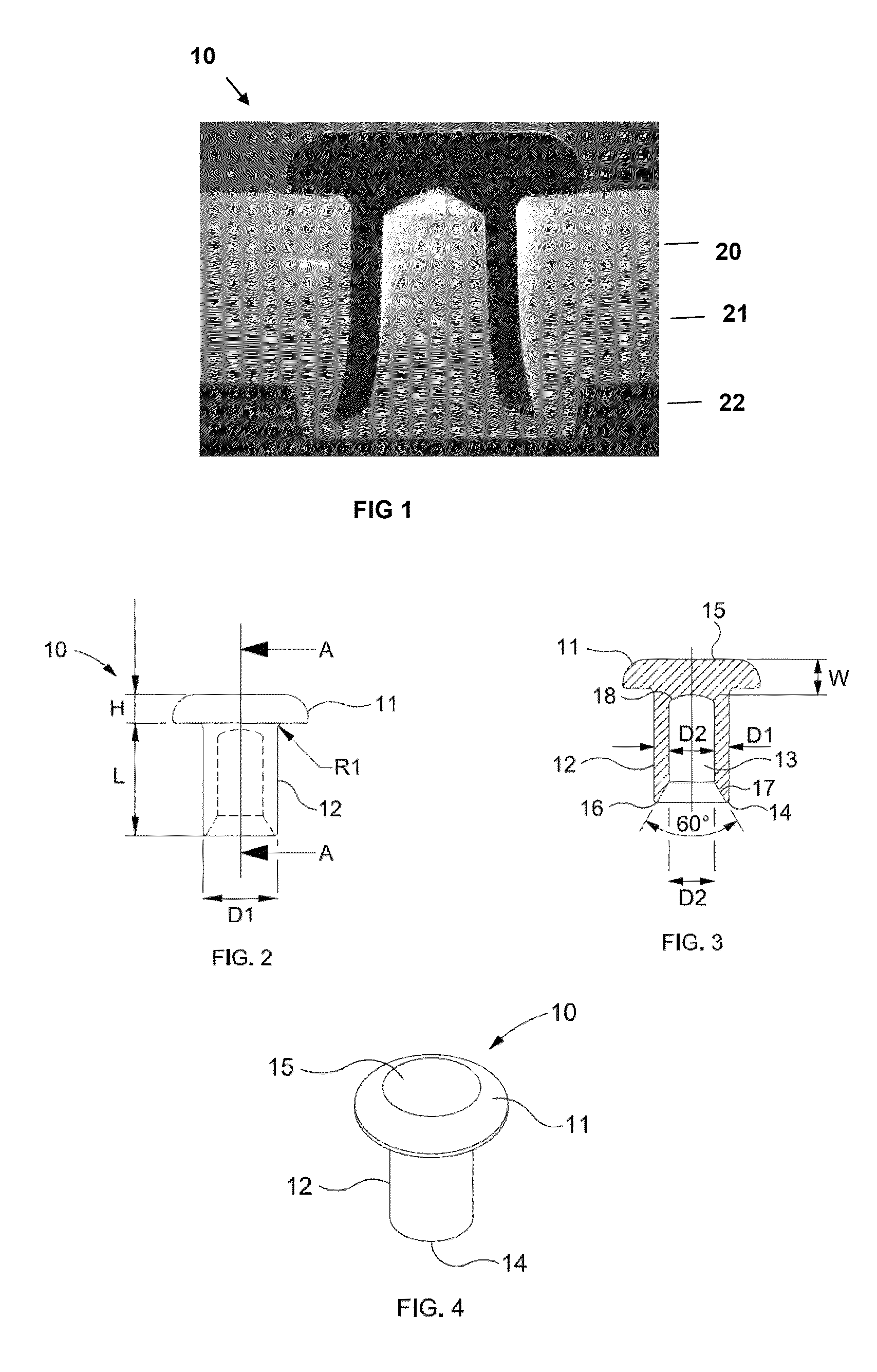
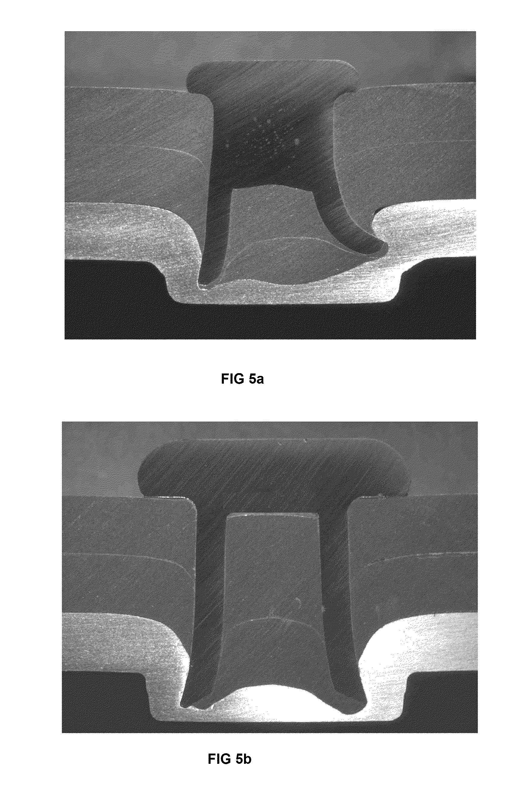
[0037]Tests performed by the inventors have established that a self-piercing rivet suitable for high strength, thick stack steels such as that described in our European patent No. 2024651 is not always suitable for thick stack, light metal alloys such as magnesium or higher strength aluminiums. These materials generally exhibit reduced ductility and thus have a tendency to fracture when used with conventional dies. The “button” of material that is deformed into the die tears during the rivet insertion process. This is undesirable as the finished joint is weakened and prone to corrosion. It has been realised by the inventors that such material should be joined by using a die with a relatively small volume die cavity (i.e. a shallow die) in order to avoid tearing. However, a reduction in the die depth serves to increase the force experienced by the rivet during insertion. Moreover, it has been found that there is a tendency for the end of the rivet shank to drag sheet material down th...


PUM

PropertyMeasurementUnit
thicknessaaaaaaaaaa
lengthaaaaaaaaaa
ultimate tensile strengthaaaaaaaaaa

Abstract

A self-piercing rivet (10) for forming joints in stacked sheets of high or low strength, light alloy metals such as aluminum and magnesium. The rivet (10) comprises a head (11) and a substantially cylindrical shank (12) that is at least partially hollow so as to define a bore (13) that extends along at least part of its length. The outside diameter (D1) of the shank (12) is at least 6 mm, the effective length of the rivet is at least 1.3 times the diameter of the shank and the bore (13) has a volume that is at least 38% of the effective solid volume of the rivet (10). The rivet geometry is such that it has enhanced column strength to withstand the high insertion forces required and a high bore volume to accommodate displaced sheet material.

Description

BACKGROUND OF THE INVENTION[0001]I. Field of the Invention[0002]The present invention relates to a self-piercing rivet of the kind that is inserted into sheet material without full penetration such that a deformed end of the rivet remains encapsulated by an upset annulus of the sheet material. It also relates to a method for forming a joint with such a rivet and to a rivet insertion system.[0003]II. Description of Related Art[0004]A self-piercing rivet generally has a head and a partially hollow shank. It is driven by a punch into the sheet material such that it pierces the top sheet and forms a mechanical interlock with the bottom sheet with the head often (but not always) flush with the upper surface of the top sheet. Since the bottom sheet is not pierced there is a reduced risk of corrosion occurring in the completed joint. Using self-piercing rivets in a joining process reduces the number of production steps as compared to conventional riveting in which a hole first has to be dr...

Claims


Application Information

Patent Timeline
Patent Type & Authority Patents(United States)
IPC IPC(8): B21J15/02F16B19/08F16B5/04
CPCF16B19/086B21J15/025F16B5/04Y10T29/49943Y10T29/49956Y10T29/5377
Inventor TRINICK, RUSSELL JOHNCLARKE, CHRISTOPHER JAMES
Owner ATLAS COPCO IAS UK LIMITED
Why Eureka
Try Eureka