Portable head support

Active Publication Date: 2018-03-15
HELD JOAN MARY
View PDF9 Cites 0 Cited by
  • Summary
  • Abstract
  • Description
  • Claims
  • Application Information

AI Technical Summary

Benefits of technology

[0004]Based on the above, the problem of providing a head support that is easily portable and can be mounted on an object such that the head support can be used in either a sitting or a prone

Problems solved by technology

However, none of the head rests are designed to be used in both a sitting and a prone posi

Method used


Image

  • Portable head support
  • Portable head support
  • Portable head support

Examples


Example

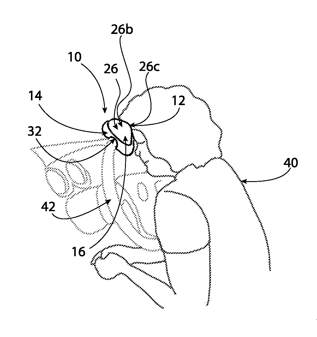
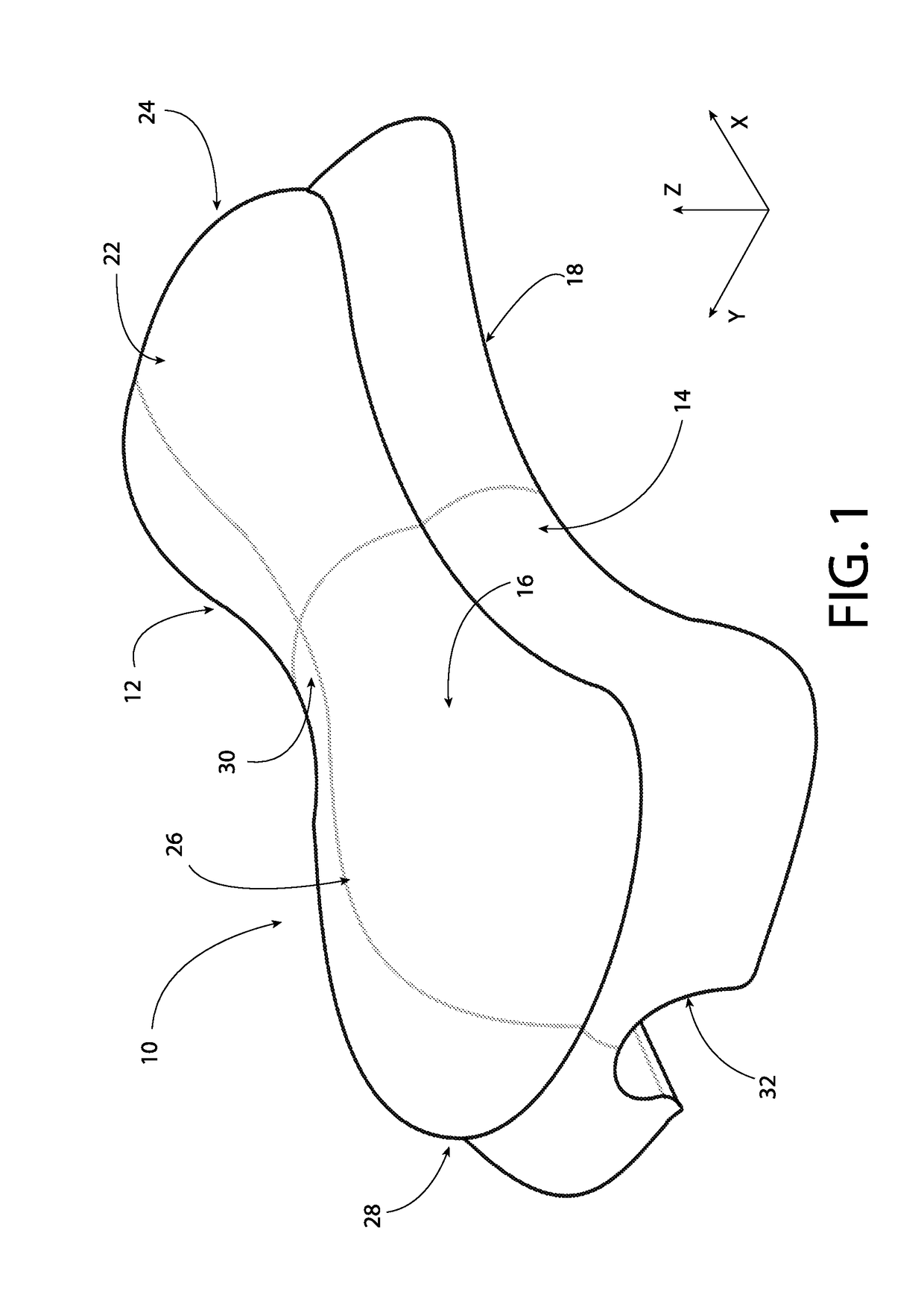
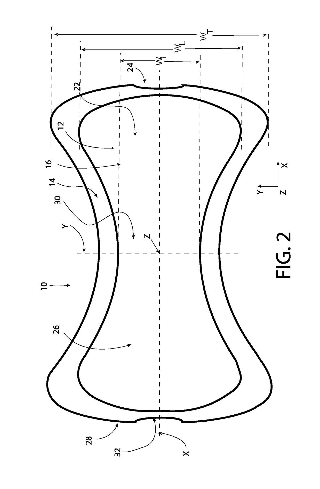
[0016]Referring now to FIGS. 1-5, a portable head support 10 is shown according to an embodiment of the invention. In general, the head support 10 includes an upper portion, shown generally at 12, and a lower portion, shown generally at 14. Both the upper portion 12 and the lower portion 14 are generally dog-bone in shape, as shown in FIG. 2. Thus, the head support 10 is generally dog-bone in shape, as shown in FIGS. 2 and 5. As used herein, a dog-bone shape is defined as a 2- or 3-dimensional compound shape, evocative of a dog biscuit or dog-bone toy with a central shaft and two lobes (analogous to femoral condyles) at each end.

[0017]As shown in FIG. 2, the lower portion 14 has a profile that extends outward from the upper portion 12. In addition, the head support 10 is substantially symmetric about two axes, the longitudinal axis, X, and the lateral or transverse axis, Y, as shown in FIGS. 2 and 3. The symmetry of the head support 10 allows the head support 10 to be bi-directional...


PUM


Abstract

A portable head support includes an upper portion having a top surface and a lower portion having a bottom surface. The top surface includes a first lobe portion at one end, a second lobe portion at an opposite end, and an intermediate or shaft portion separating the first and second lobe portions. The intermediate or shaft portion has a height, HI, and a length, LI, with respect to the bottom surface and the first and second lobe portions each have a height, H2, and a length, LL with respect to the bottom surface. The height, H1, and the length, LI, of the intermediate or shaft portion are less than the height, HL, and the length, LL, of the first and second lobe portions. The bottom surface includes a groove for allowing the portable head support to be mounted onto an object.

Description

FIELD OF THE INVENTION[0001]The invention relates, in general, to pillows or head supports and, more particularly to a portable head support on which a person can rest his or her head to sleep or to relax while in a sitting position or in a prone position.BACKGROUND OF THE INVENTION[0002]Some head rests are designed to be mounted on a table during a medical procedure or during a massage therapy session. In this example, the user is in a prone position. In another example, some head rests are designed with angled surfaces to be placed on a flat surface to allow a user to place their forehead and chin on the head rest while in a sitting position. However, none of the head rests are designed to be used in both a sitting and a prone position.[0003]In addition, most head rest designs do not allow the head rest to be easily portable. Thus, there is a need to provide an improved head support design that solves the problems mentioned above.SUMMARY OF THE INVENTION[0004]Based on the above, t...

Claims


Application Information

Patent Timeline
IPC IPC(8): A47G9/10
CPCA47G2009/1018A47G9/1054
Inventor HELD, JOAN MARY
Owner HELD JOAN MARY
Why Eureka
Try Eureka