Apparatus and method for correcting orthodontic malocclusions

Inactive Publication Date: 2018-03-15
HA DANG
View PDF12 Cites 53 Cited by
  • Summary
  • Abstract
  • Description
  • Claims
  • Application Information

AI Technical Summary

Benefits of technology

[0022]h. allowing a sufficient time for movement of the tooth or teeth in need of repositioning caused b

Problems solved by technology

While effective, braces have several disadvantages, including aesthetic appearance, generally painful, and unable to move teeth with exact precision.
Most significantly, sequential appliances are only effective at correcting relative minor malocclusi

Method used


Image

  • Apparatus and method for correcting orthodontic malocclusions
  • Apparatus and method for correcting orthodontic malocclusions
  • Apparatus and method for correcting orthodontic malocclusions

Examples


Embodiment Construction

[0034]Embodiments of the present invention provide a system and method for using magnetic force to incrementally move teeth using a plurality of individual appliances, where each appliance successively moves one or more teeth from a starting position to a final position according to a predetermined treatment plan based upon a computer model of the subject.

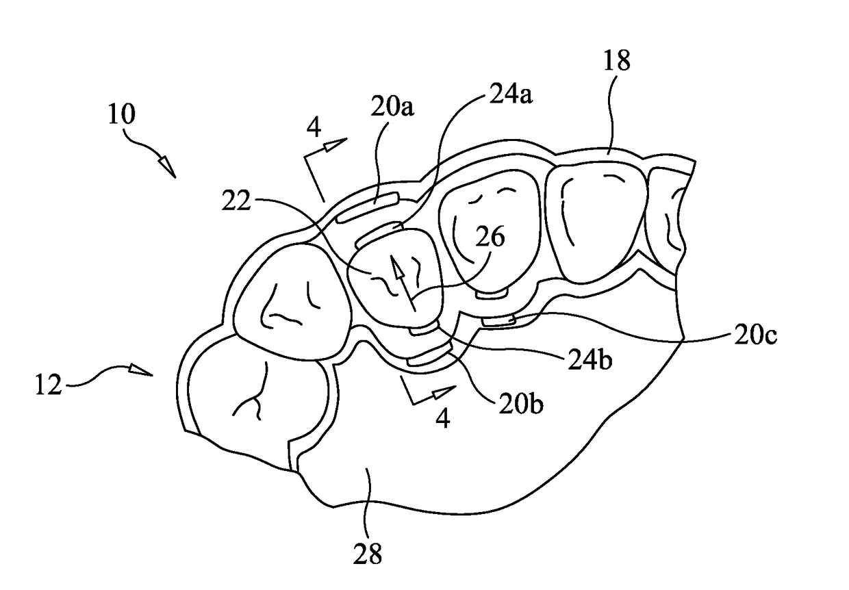
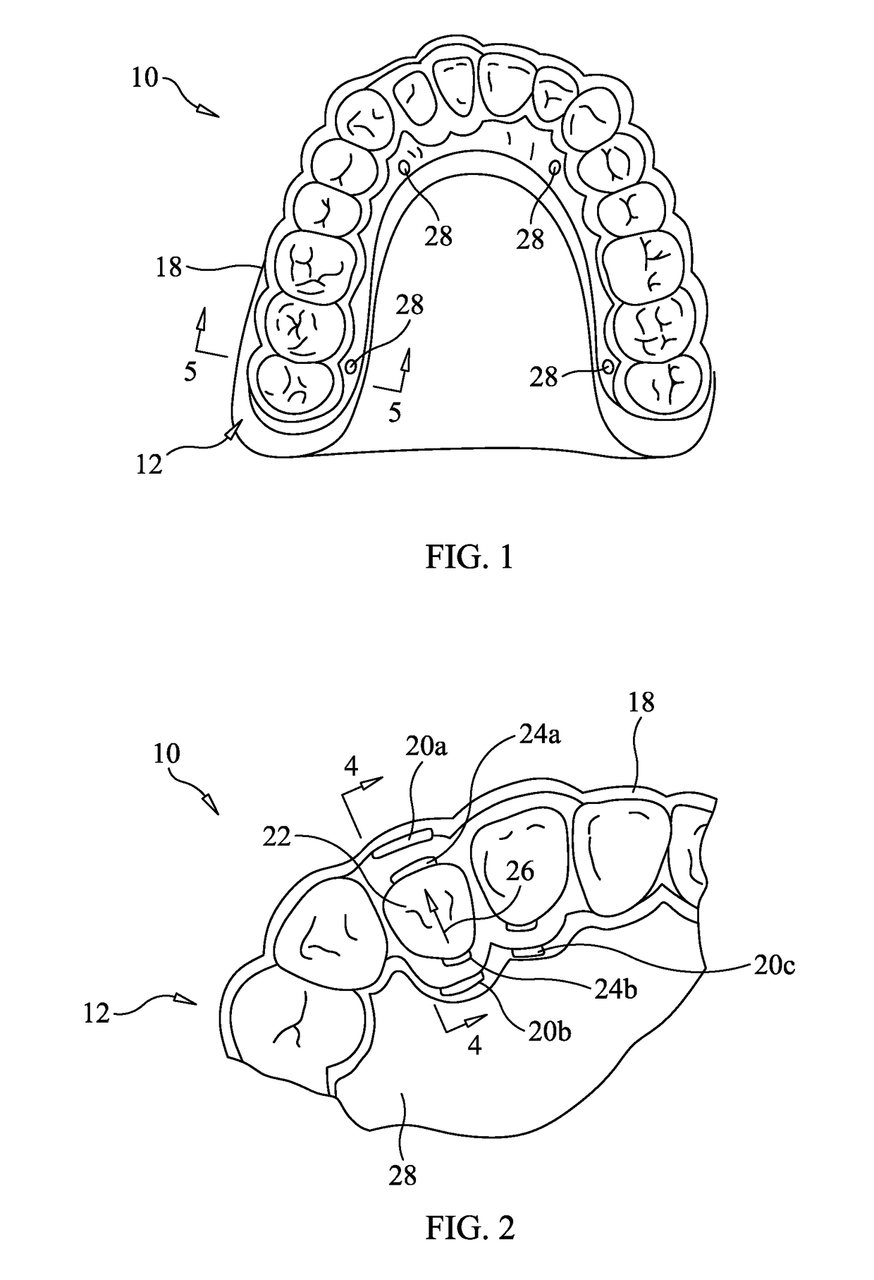
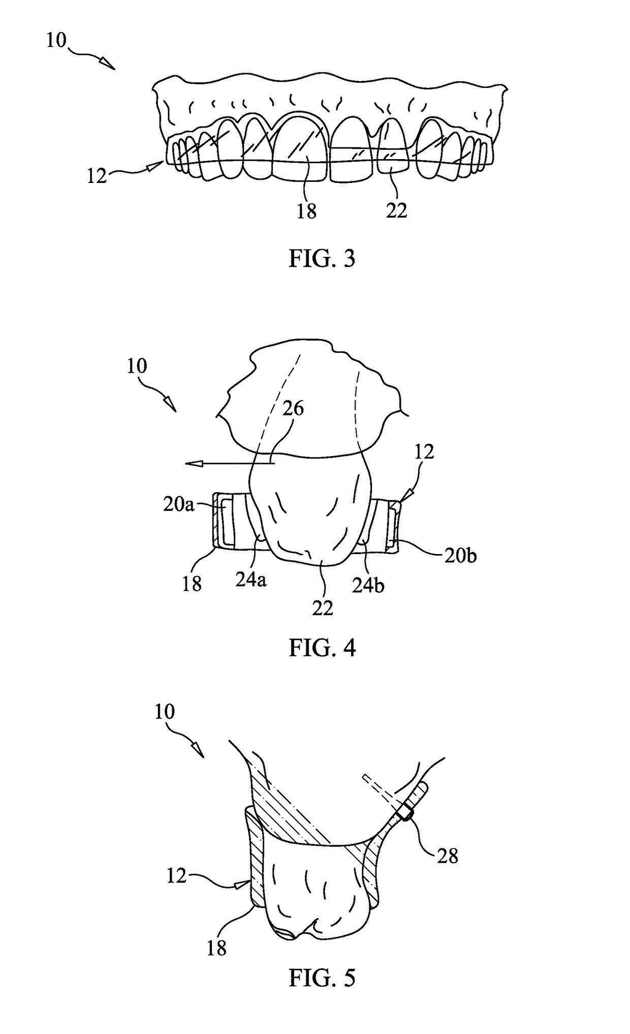
[0035]With reference now to FIGS. 1-5, there is representatively illustrated a set of teeth and a system 10 for repositioning one or more teeth using magnetic forces. The system includes an appliance 12, one or more first magnets 20a-20c disposed on the appliance 12, and one or more second magnets 24a-24b bonded to one or more teeth needing repositioning.

[0036]Representatively illustrated, the appliance 12 comprises a body 18 having a general loop form configured to generally follow the contour and shape of the subject's teeth. The body 18 is formed to contact vertical surfaces of the teeth that are not being moved and provide a sp...


PUM


Abstract

A sequential orthodontic appliance includes a body and one or more first magnets disposed on the body and arranged to provide either repulsive or attractive force between one or more second magnets disposed on a surface of a tooth in need of repositioning. One or more temporary anchorage devices are used to secure the appliance to a person with the body disposed approximate the tooth.

Description

CROSS-REFERENCE TO RELATED APPLICATION[0001]This application claims the benefit of U.S. Provisional Application No. 62 / 495,426, filed Sep. 14, 2016, the entirety of which is incorporated herein by reference.FIELD OF THE INVENTION[0002]The present invention relates to the correction of orthodontic malocclusions and, more particularly, correcting malocclusions using magnet force between magnets disposed on a removable appliance and corresponding magnets placed on the teeth.BACKGROUND OF THE INVENTION[0003]Malocclusion is a misalignment or incorrect relation between the upper and lower teeth when the jaw closes. Orthodontic treatment is used to correct teeth and jaw positioning so that the upper and lower teeth fit together properly. Historically, orthodontic treatment to correct malocclusion has been accomplished by using direct contact, static force to induce bone remolding and teeth repositioning. The most common method is braces, which have an archwire interface with brackets that ...

Claims


Application Information

Patent Timeline
IPC IPC(8): A61C7/00A61C7/08
CPCA61C7/006A61C7/08A61C8/0096
Inventor HA, DANG
Owner HA DANG
Why Eureka
Try Eureka