Programmable orthodontic indexing guide and bracket pin assembly and method of use

Inactive Publication Date: 2018-03-15
RUDMAN ROBERT T
View PDF14 Cites 20 Cited by
  • Summary
  • Abstract
  • Description
  • Claims
  • Application Information

AI Technical Summary

Benefits of technology

[0007]The function of the indexing pin is to precisely lock an orthodontic bracket in its computer chosen position to a clear orthodontic tray with minimal or no contact between the tray and the bracket. A tray is then vacuum molded over the model. Th

Problems solved by technology

The current state of the art requires digital trays rigid enough to not allow the brackets to migrate which makes the trays difficult to remove once the brackets have been placed in the mouth.
The removal difficulty increases the more crooked th

Method used


Image

  • Programmable orthodontic indexing guide and bracket pin assembly and method of use
  • Programmable orthodontic indexing guide and bracket pin assembly and method of use
  • Programmable orthodontic indexing guide and bracket pin assembly and method of use

Examples


Example

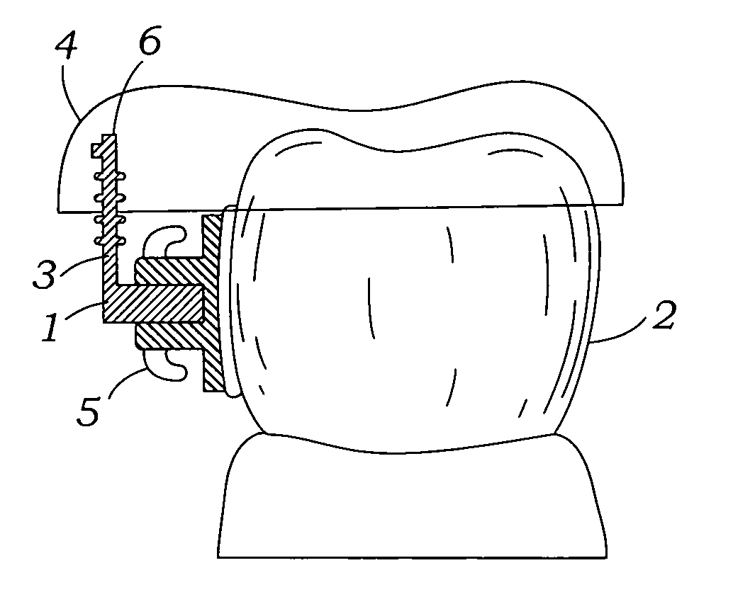
[0027]The invention is comprised of a digital indirect bonding assembly 1. FIG. 1 discloses the digital indirect bonding assembly 1 on a tooth 2. The assembly is comprised of a male indexing pin 3 with a second tail end 6, and an occlusal index tray 4. The indexing pin 3 is engaged with an orthodontic bracket 5. The indexing pin 3 is embedded in the occlusal index tray 4 at the second end 6. The bracket 5 position is determined by the position the male indexing pin 3 and is held in with ridges 8 and a geometric end 9, as shown in FIG. 2.

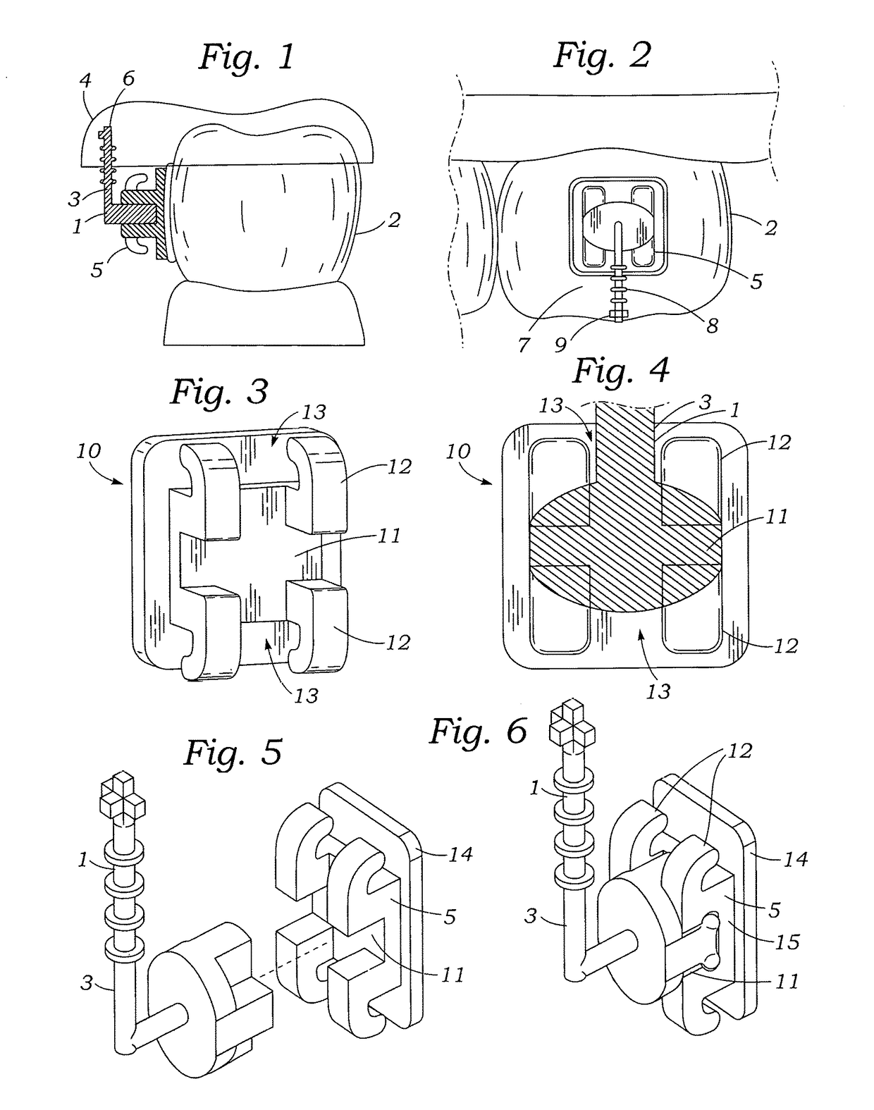
[0028]FIG. 2 shows the bracket 5 attached to a tooth 2 with the longitudinal tail 7 extending occlusally from the bracket 5. The longitudinal tail 7 has ridges 8 and a geometric end 8 to enhance the positional locking of the longitudinal tail 7 in the occlusal index tray 4. The bracket end of the male indexing pin 3 is snap fitted to the bracket 5.

[0029]FIG. 3 discloses an arch wire slot 11, bracket tie wings 12 and an interwing area 13 between the t...


PUM


Abstract

The present invention is directed to indirect bonding orthodontic brackets to a patient's teeth. A geometric index pin is attached to the orthodontic bracket enabling the orthodontic bracket to be precisely held by a plastic tray. A computer program positions the index pin/bracket combination for a patient's teeth in a determined position and designs the tray to carry each bracket to the patient's tooth in its computer selected position. The index pin eliminates the necessity for the tray material to enclose the bracket which results in a dental tray one third the normal dental tray which saves tray material and reduces the print time of the tray. The ease of removal of the tray from the teeth after placement of the brackets is enhanced by clipping the index pins with a pin cutter.

Description

FIELD OF THE INVENTION[0001]The present invention relates to the field of orthodontics, more particularly to computer programmed indirect bracket bonding, more specifically to bracket holders and transfer trays.BACKGROUND OF THE INVENTION[0002]Orthodontics is a branch of dentistry involving the treatment of irregularities in the teeth and jaws, including the use of braces. Orthodontic brackets are bonded to the teeth where a wire, called an arch wire, is attached to the bracket. The dentist determines the position of each bracket. The more accurately the brackets are placed the less the wires must be adjusted to achieve a perfect result. It is common that brackets must be repositioned on the teeth. The concept of not adjusting arch wires was advanced by Dr. Andrews when he developed the straight wire appliance (1970). The next concept was the brackets could be fitted more accurately on models of a patient's teeth. The brackets are positioned on the model and a dental tray was vacuum...

Claims


Application Information

Patent Timeline
IPC IPC(8): A61C7/14A61C7/00A61C7/34
CPCA61C7/146A61C7/002A61C7/34A61C7/023A61C7/143
Inventor RUDMAN, ROBERT T
Owner RUDMAN ROBERT T
Why Eureka
Try Eureka