Package sealer for slicing machine

Active Publication Date: 2005-09-08
KUCHLER FRITZ
View PDF4 Cites 0 Cited by
  • Summary
  • Abstract
  • Description
  • Claims
  • Application Information

AI Technical Summary

Benefits of technology

[0014] A vertically shiftable deposition plate is connected in accordance with the invention to the drive and forms the surface. The heaters are in the deposition plate, each extending in a straight line along the edge of the deposition plate to define a rectangular deposition field. This makes it possible to keep the supply cable for these normally electrical heaters safely out of the way. It is of course also possible to hold the deposition plate stationary and lower a frame carrying the sealing bars.
[0015] Sensors a

Problems solved by technology

The difficulty with this arrangement is that it is very bulky.
It is horizon

Method used


Image

  • Package sealer for slicing machine
  • Package sealer for slicing machine
  • Package sealer for slicing machine

Examples


Example

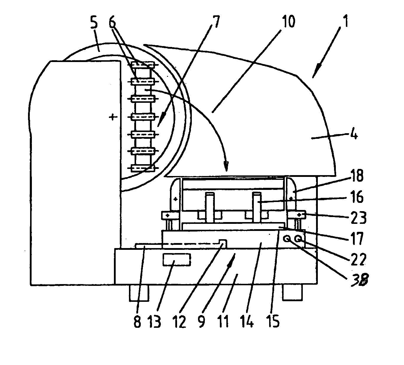
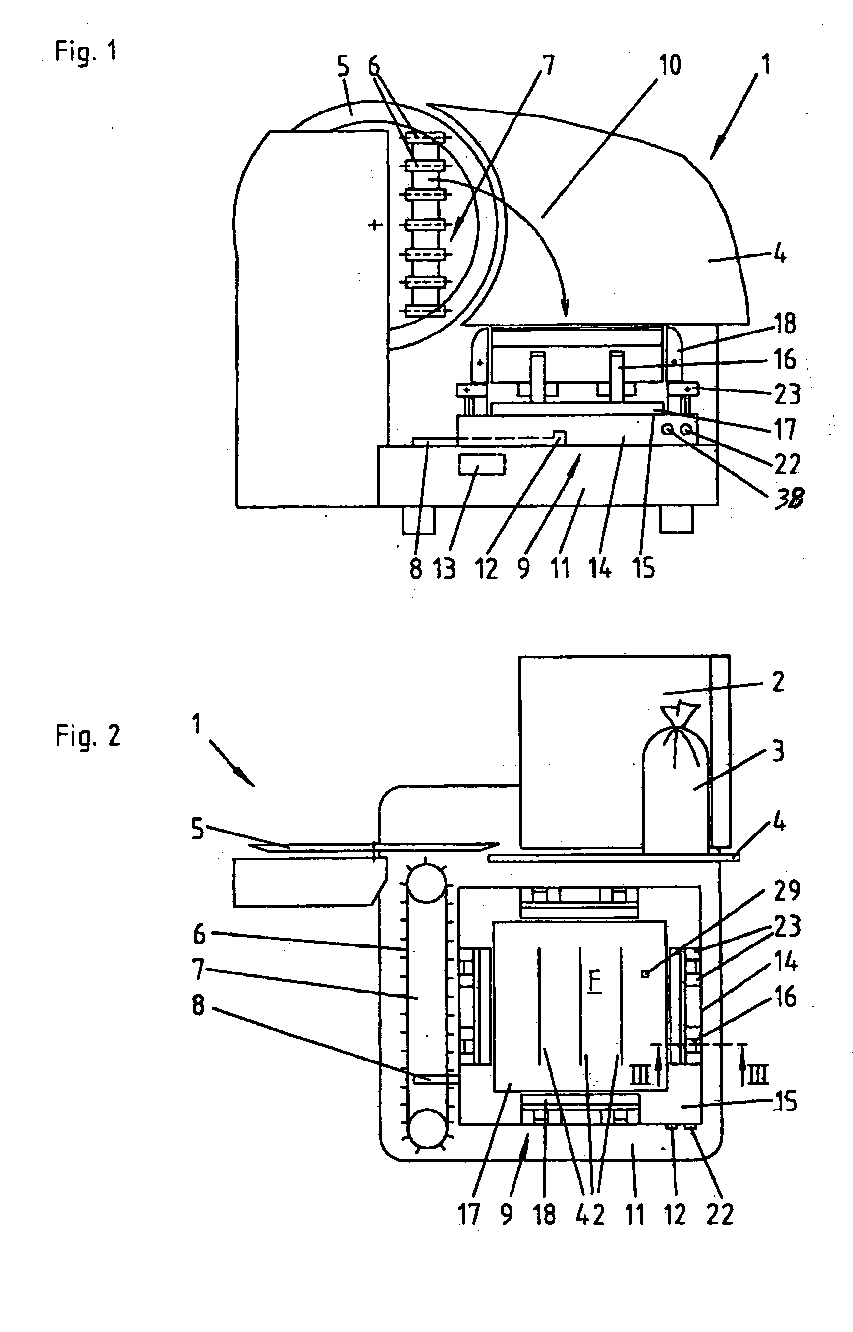
[0023] As seen in FIGS. 1 and 2, a slicing machine 1 according to the invention has a housing 11 that carries a slide or carriage 2 adapted to hold a foodstuff 3, here a wurst, which is pressed against a stationary abutment plate 4 and moved past a standard circularly planar blade 5 to cut slices 27 (FIGS. 3-8) from it. Point-carrying feeder chains 6 orbiting on a frame 7 moved by a controller 13 deposit the slices 27 as shown by arrow 10 on a horizontal deposition plate or surface 17 of a sealer 9 that has ribs 42 and that is moved about via an entrainment lug 12 of a conveyor element 8 by the controller 13, the slices 27 being dropped as is well known in the art into an array which may be a simple stack or extended in some pattern depending on how the controller 13 moves the lug 12. The controller 12 has a timer switch 38 allowing the fuse time to be adjusted, it normally being set between 1.5 sec and 3.0 sec.

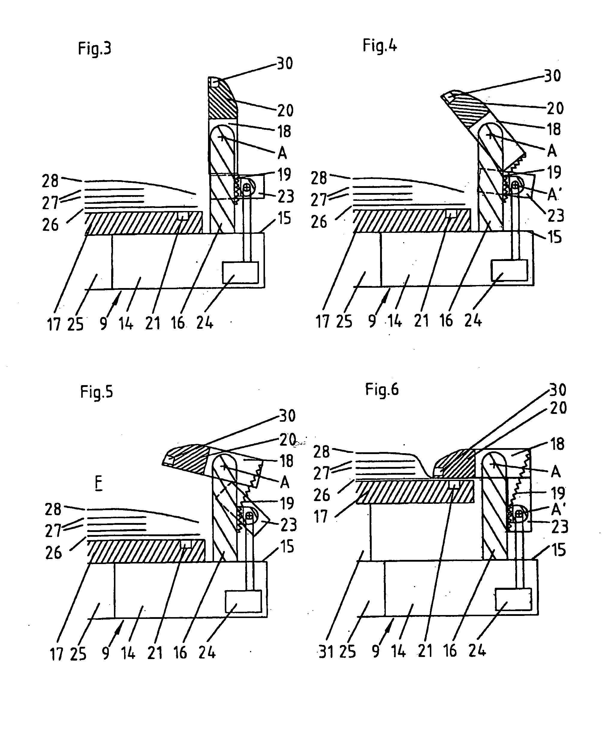
[0024] According to the invention as shown in FIGS. 3 to 6 the sealer 9...


PUM

PropertyMeasurementUnit
Displacementaaaaaaaaaa
Compressibilityaaaaaaaaaa

Abstract

A slicing machine has a deposition surface adapted to support a fusible bottom sheet. Slices are cut from a foodstuff and deposited as a stack on the bottom sheet on the surface between edges of the surface so that a fusible top sheet can be placed atop the stack. Respective bars at the surface edges have bar edges and are each pivotal between a working position projecting over the surface with the bar edges aligned vertically with the respective surface edges and rest positions retracted from above the sheet on the surface. Actuators can pivot the bars from their rest positions into their working positions. Heaters are provided in at least some of the edges. In the working positions the sheet edges are pinched between the bar edges and the heated surface to bond the edges together.

Description

FIELD OF THE INVENTION [0001] The present invention relates to a package sealing unit. More particularly this invention concerns a sealer for use on a slicing machine. BACKGROUND OF THE INVENTION [0002] A standard slicing machine such as described in U.S. Pat. No. 6,666,006 has a main housing having a horizontal conveyor surface and a subassembly in the main housing for cutting slices from a foodstuff and depositing them on the conveyor surface. A supply housing immediately upstream of the main housing carries a supply roll of flexible strip and mechanism for feeding the flexible strip downstream toward the main housing. A cutter on the supply housing can sever a sheet from a leading end of the flexible strip. A gripper above the surface is displaceable between an upstream position generally at the cutter and a downstream position downstream of the surface. The gripper is closable to grip the leading end of the flexible strip and openable to release it. A controller connected to the...

Claims


Application Information

Patent Timeline
IPC IPC(8): B65B51/14
CPCB29C66/8244B65B51/148B29C65/18B29C66/1122B29C66/8742B29C66/8322B29C66/8324B29C66/849B29C66/43B29C66/24245B29C66/3452B29C66/81463B29C66/8221B29C66/8225B29C66/8227B29C66/8432B29C66/929
Inventor KUCHLER, FRITZ
Owner KUCHLER FRITZ
Why Eureka
Try Eureka