Multi-claw self-adjusting breathing-type smoke exhaust ventilator
A technology for range hood and range hood, which is applied in the direction of removing range hood, heating method, and household heating, etc., to achieve the effect of facilitating oil pollution removal, improving efficiency and reducing noise.
- Summary
- Abstract
- Description
- Claims
- Application Information
AI Technical Summary
Problems solved by technology
Method used
Image
Examples
Embodiment 1
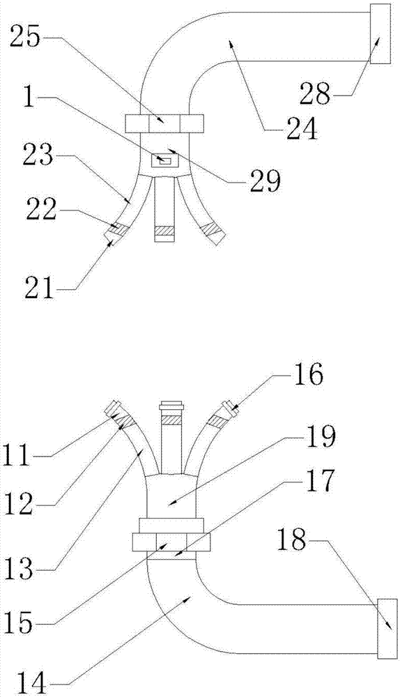
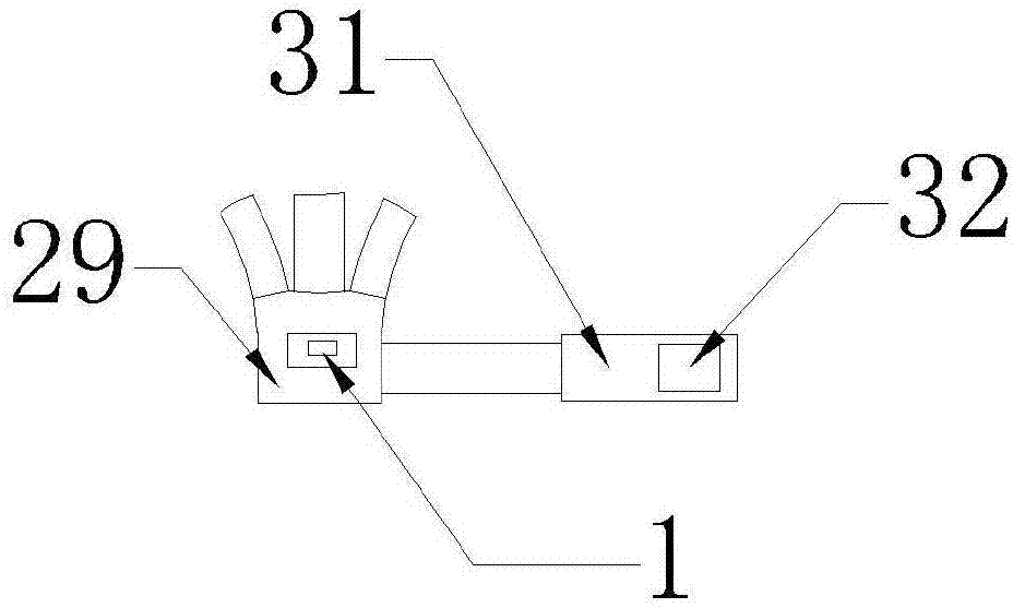
[0025] A multi-claw self-regulating breathing range hood, such as Figure 1-2 As mentioned above, it includes a cooktop, and also includes a range fume device I, an exhalation device II and a control panel 1. The range fume device I and the exhalation device II are installed on the range top. In this embodiment, the control panel 1 is set on On the exhalation device II; the stove value here refers to all the equipment in the kitchen except the range hood, including walls, chopping boards, etc. The range hood is used near the stove.
[0026] The oil fume suction device I includes a multi-claw unit I, a mobile unit I19, an oil fume exhaust unit I and a wind force unit I, and the multi-claw unit I, the mobile unit I19 and the oil fume exhaust unit I are sequentially connected.
[0027] The multi-claw unit I includes at least two claw tubes I, which are made of TPU-wrapped stainless steel. In this embodiment, there are four, one of which is blocked and not shown; the claw tube I i...
Embodiment 2
[0043] Different from Example 1, in this embodiment, No. 2 pipeline I13 and No. 2 pipeline II 23 are bendable shrinkage tubes, and the length of No. 2 pipeline II 23 can be adjusted so that No. 2 pipeline II 23 moves No. 1 pipeline II 21 to It is closer to the position with high oil fume concentration. Similarly, the No. 2 pipeline I13 moves the No. 1 pipeline I11 closer to the position with high oil fume concentration, and the spatial distribution of multi-claw unit I and multi-claw unit II on the cooktop can also be changed. , to achieve the storage effect and effectively save space. In addition, the control panel 1 can control the up and down movement of the rotary valve I12 and the rotary valve II22 to realize automatic control.
Embodiment 3
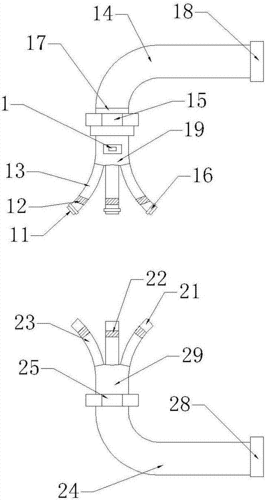
[0045] Different from Example 1, in this example, if image 3 As shown, the transmission mechanism is connected with the mobile unit I19, which can realize the linear reciprocating movement of the mobile unit, and the suction device I is installed on the upper side of the cooktop, wherein, compared with the mobile unit I19 or the oil fume exhaust unit I, the multi-claw unit I Located at the bottom of the device; the control panel 1 is electrically connected to the mobile unit I19, and can control the movement of the multi-claw unit I to a position with a high oil fume concentration; Oil fume unit II, multi-claw unit II is located above the device; the transmission mechanism includes a roller 33 arranged on the mobile unit I19, a slide rail 34 arranged on the cooktop, a rotating motor 35 driving the roller 33 and two motors controlling the rotating motor 35 No. 1 controller 36 and No. 2 controller 36 are electrically connected to the control panel 1 .
PUM
 Abstract
Description
Claims
Application Information
 - R&D
- Intellectual Property
- Life Sciences
- Materials
- Tech Scout
- Unparalleled Data Quality
- Higher Quality Content
- 60% Fewer Hallucinations
Browse by: Latest US Patents, China's latest patents, Technical Efficacy Thesaurus, Application Domain, Technology Topic, Popular Technical Reports.
© 2025 PatSnap. All rights reserved.Legal|Privacy policy|Modern Slavery Act Transparency Statement|Sitemap|About US| Contact US: help@patsnap.com


