Pneumatic Tire

Active Publication Date: 2018-03-22
YOKOHAMA RUBBER CO LTD
View PDF7 Cites 16 Cited by
  • Summary
  • Abstract
  • Description
  • Claims
  • Application Information

AI Technical Summary

Benefits of technology

[0005]The present technology provides a pneumatic tire capable of improving braking performance on we

Problems solved by technology

However, extending this to enhance another performance so that good performances in three areas are achieved in a compatible manner is difficult.
Thus, the rigidity of the land portion decreases and the uneven wear resistance

Method used


Image

  • Pneumatic Tire
  • Pneumatic Tire
  • Pneumatic Tire

Examples


Example

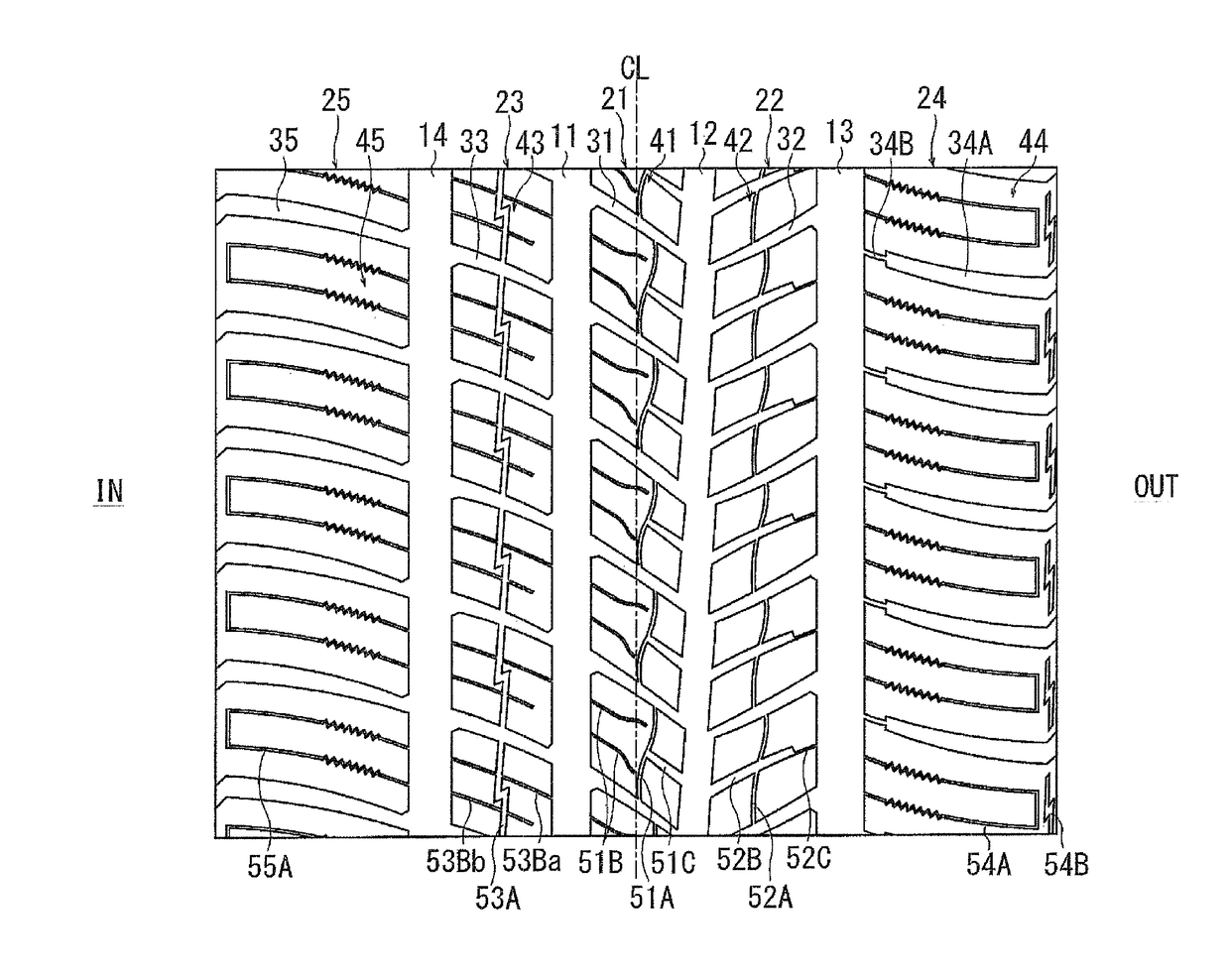
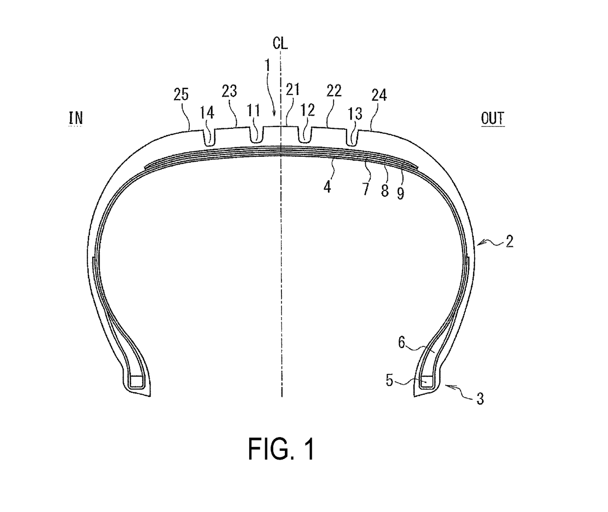
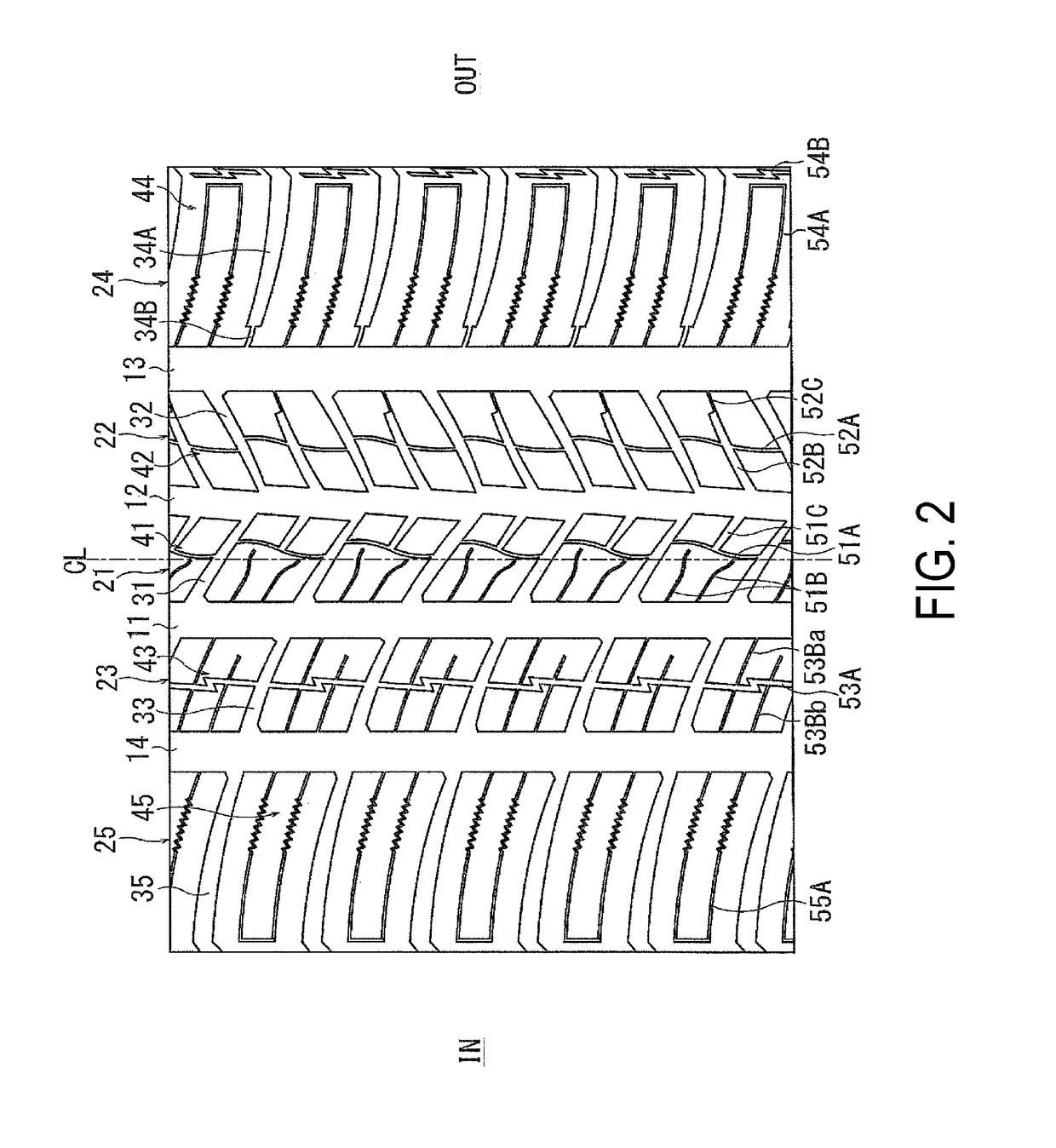
[0070]Thirteen types of pneumatic tires, Conventional Example 1, Comparative Example 1, and Examples 1 to 11 were manufactured. The manufactured pneumatic tires had a tire size of 205 / 55R16 91V, the cross sectional shape illustrated in FIG. 1, the tread pattern illustrated in FIG. 2 as a base, and set with the values listed in Table 1 for the following parameters: presence of first circumferential auxiliary groove, type of groove that opens to the inner side with respect to the vehicle when the tire is mounted on the vehicle (vehicle inner side), type of groove that opens to the outer side with respect to the vehicle when the tire is mounted on the vehicle (vehicle outer side), angle α formed by the set of lateral narrow grooves, angle β formed by the first circumferential narrow groove and the first lateral auxiliary groove, the ratio of the area of the region with the smallest area of the five regions divided by the first circumferential narrow groove and the set of lateral narrow...

Example

[0071]Note that the Comparative Example 1 has substantially the same tread pattern as Example 1; however, the groove that opens to the vehicle inner side (first lateral narrow groove in an embodiment of the present technology) is an auxiliary groove with a groove width greater than the narrow grooves.

[0072]The 13 types of pneumatic tires were evaluated for wet performance, snow performance, and wear resistance performance by the evaluation methods described below, and the results are also shown in Table 1.

Wet Performance

[0073]The test tires were mounted on wheels with a rim size of 16×6.5 JJ, inflated to an air pressure of 200 kPa, and mounted on a front wheel drive passenger vehicle (test vehicle) with an engine displacement of 1.6 L. A driving test was performed by a test driver on a wet road surface test course with a 1 mm deep film of water. The distance (braking distance) was measured from the point where the brakes were applied at an initial speed of 100 km / h to the point wher...


PUM


Abstract

A pneumatic tire includes a first block formed by first lug grooves defining a first land portion that is defined by a first main groove and a second main groove. The first block includes: a first circumferential narrow groove extending in the tire circumferential direction with at least one end communicating with one of the first lug grooves, a set of two lateral narrow grooves extending in the tire width direction with one end communicating with the first main groove, a first lateral auxiliary groove extending in the tire width direction with a first end communicating with the second main groove and a second end communicating with the first circumferential narrow groove, the second end of the first lateral auxiliary groove being disposed at a position in the tire circumferential direction between end portions of the set of first lateral narrow grooves proximal to the first circumferential narrow groove.

Description

TECHNICAL FIELD[0001]The present technology relates to a pneumatic tire and particularly relates to a pneumatic tire capable of improving braking performance on wet road surfaces and snowy road surfaces in a compatible manner and uneven wear resistance performance.BACKGROUND ART[0002]Generally, all-season pneumatic tires used all year round are required to have excellent running performance (for example, braking performance) on various road surfaces such as dry road surfaces, wet road surfaces, and snowy road surfaces, as well as having excellent uneven wear resistance performance. In the art, pneumatic tires designed to achieve good performance in a compatible manner in two areas among such various areas are known. Examples include a pneumatic tire that includes, in a tread surface, two circumferential grooves extending in the tire circumferential direction arranged side by side in the tire width direction, and lateral grooves disposed in land portions formed between the circumfere...

Claims


Application Information

Patent Timeline
IPC IPC(8): B60C11/12B60C11/03
CPCB60C11/1236B60C11/0304B60C11/0306B60C11/1204B60C11/0302B60C2011/1213B60C11/11B60C2011/0348B60C2011/0358B60C2011/0381B60C2011/1209B60C11/03B60C11/12B60C2011/0353
Inventor SUZUKI, TAKUMI
Owner YOKOHAMA RUBBER CO LTD
Why Eureka
Try Eureka