Brake control device for motorcycle

Active Publication Date: 2011-02-24
HONDA MOTOR CO LTD
View PDF9 Cites 8 Cited by
  • Summary
  • Abstract
  • Description
  • Claims
  • Application Information

AI Technical Summary

Benefits of technology

[0016]According to an embodiment of the present invention, in the brake control device of the front-wheel and rear-wheel interlocking brake system, in the state in which the rear-wheel ABS is inactive, the front-wheel and rear-wheel interlocking brake is not started until the rear-wheel brake operating force falls within a greater force range. This allows the braking focusing on vehicle body attitude control in which the action of the front-wheel brake is much smaller than that of the rear-wheel brake. On the other hand, in the state in which the rear-wheel ABS is active, the front-wheel and rear-wheel interlocking brake is started when the rear-wheel brake ope

Problems solved by technology

However, in the case where the front-wheel and rear-wheel interlocking brake system with the ABS control is employed, there is a possibility that, once the re

Method used


Image

  • Brake control device for motorcycle
  • Brake control device for motorcycle
  • Brake control device for motorcycle

Examples


Example

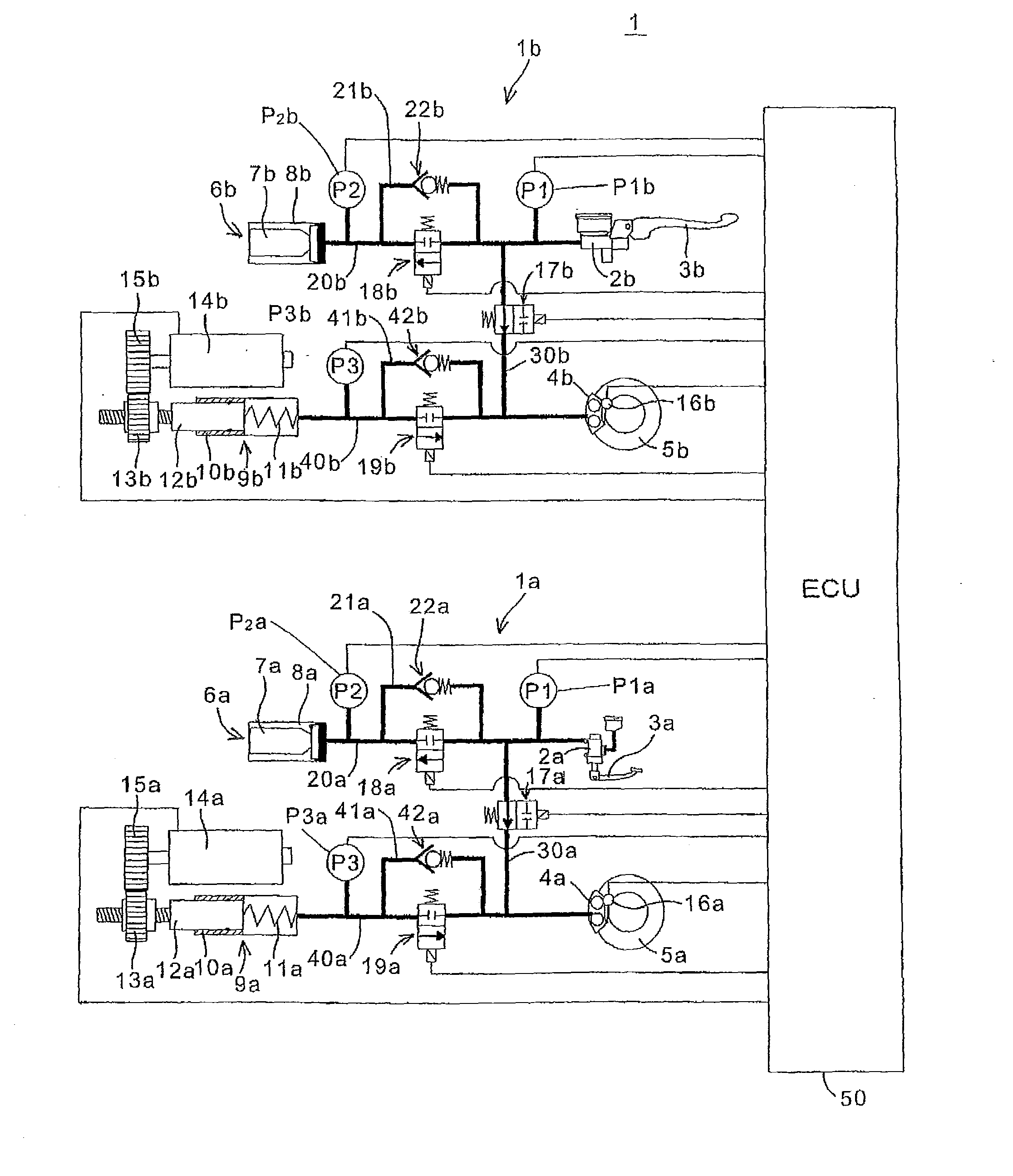
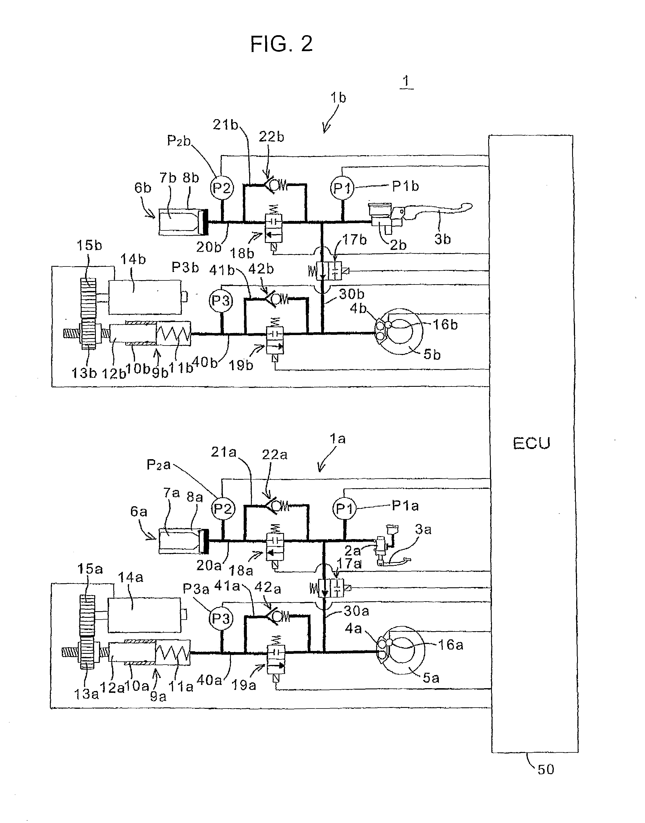
[0026]Hereinafter, one embodiment of the present invention will be described with reference to the accompanying drawings. FIG. 2 is a hydraulic circuit diagram of a brake control device for a motorcycle according to one embodiment of the present invention. The brake control device 1 is composed of a rear-wheel braking circuit 1a and a front-wheel braking circuit 1b which are independent of each other, and an ECU 50 serving as control means for controlling the braking circuits 1a and 1b.

[0027]In FIG. 2, elements of the brake control device 1 are referred to by the reference signs each consisting of a numeral and a lower-case alphabetic letter designate, in which the same numerals designate similar portions of the front-wheel and rear-wheel braking circuits, and the lower-case letters “a” designate the elements of the rear-wheel side and the lower-case letters “b” designate the elements of the front-wheel side. Except for a brake operating unit 3 composed of a brake pedal 3a and a br...


PUM


Abstract

To prevent deterioration of sports driving performance due to the actuation of an ABS in a front-wheel and rear-wheel interlocking brake system of a brake-by-wire system. A brake interlock determining portion starts a front-wheel brake when input hydraulic pressure by a brake operation (pedal operation) on a rear-wheel becomes equal to or greater than an interlocking brake starting pressure value. A threshold selecting switch allows switching of the interlocking brake starting pressure value between when the ABS is active and when the ABS is inactive. When the ABS is active, a lower pressure value is selected as the interlocking brake starting pressure value. When the ABS is inactive, an upper pressure value is selected as the interlocking brake starting pressure value.

Description

CROSS-REFERENCE TO RELATED APPLICATIONS[0001]The present application claims priority under 35 USC 119 to Japanese Patent Application No. 2009-190039 filed on Aug. 19, 2009 the entire contents of which are hereby incorporated by reference.[0002]1. Field of the Invention[0003]The present invention relates to a brake control device for a motorcycle. More particularly, to a brake control device for a motorcycle which actuates front-wheel and rear-wheel brakes in an interlocking manner by a pedal operation.[0004]2. Description of Background Art[0005]A brake control device for a motorcycle is known wherein a front-rear interlocking brake system allows a front-wheel brake as well as a rear-wheel brake to be actuated in an interlocking manner by only operating a brake pedal. For example, JP-A No. H11-5580 discloses a braking device for a motorcycle in which front and rear wheels can be braked by operation of either a brake lever and a brake pedal. When the brake lever is operated, the distr...

Claims


Application Information

Patent Timeline
IPC IPC(8): B60T8/176B60T8/34B60T8/1761
CPCB60T8/1706
Inventor NISHIKAWA, YUTAKATAKENOUCHI, KAZUYANANRI, TAKEHIKOTANI, KAZUHIKO
Owner HONDA MOTOR CO LTD
Why Eureka
Try Eureka