Bicycle brake shoe

Inactive Publication Date: 2006-07-06
LIN A P
View PDF10 Cites 8 Cited by
  • Summary
  • Abstract
  • Description
  • Claims
  • Application Information

AI Technical Summary

Benefits of technology

[0008] One object of the present invention is to provide bicycle br

Problems solved by technology

In the case of the anodized rim, the braking surfaces are hard and shiny which provides good braking performance in dry conditions, but poor braking performance in wet conditions.
While such improved rubber brake shoes provide good wet and dry performance, such brake shoes with alumina c

Method used


Image

  • Bicycle brake shoe
  • Bicycle brake shoe
  • Bicycle brake shoe

Examples


Example

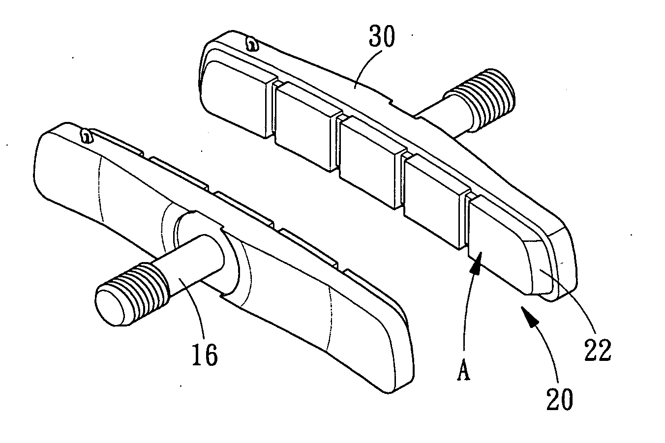
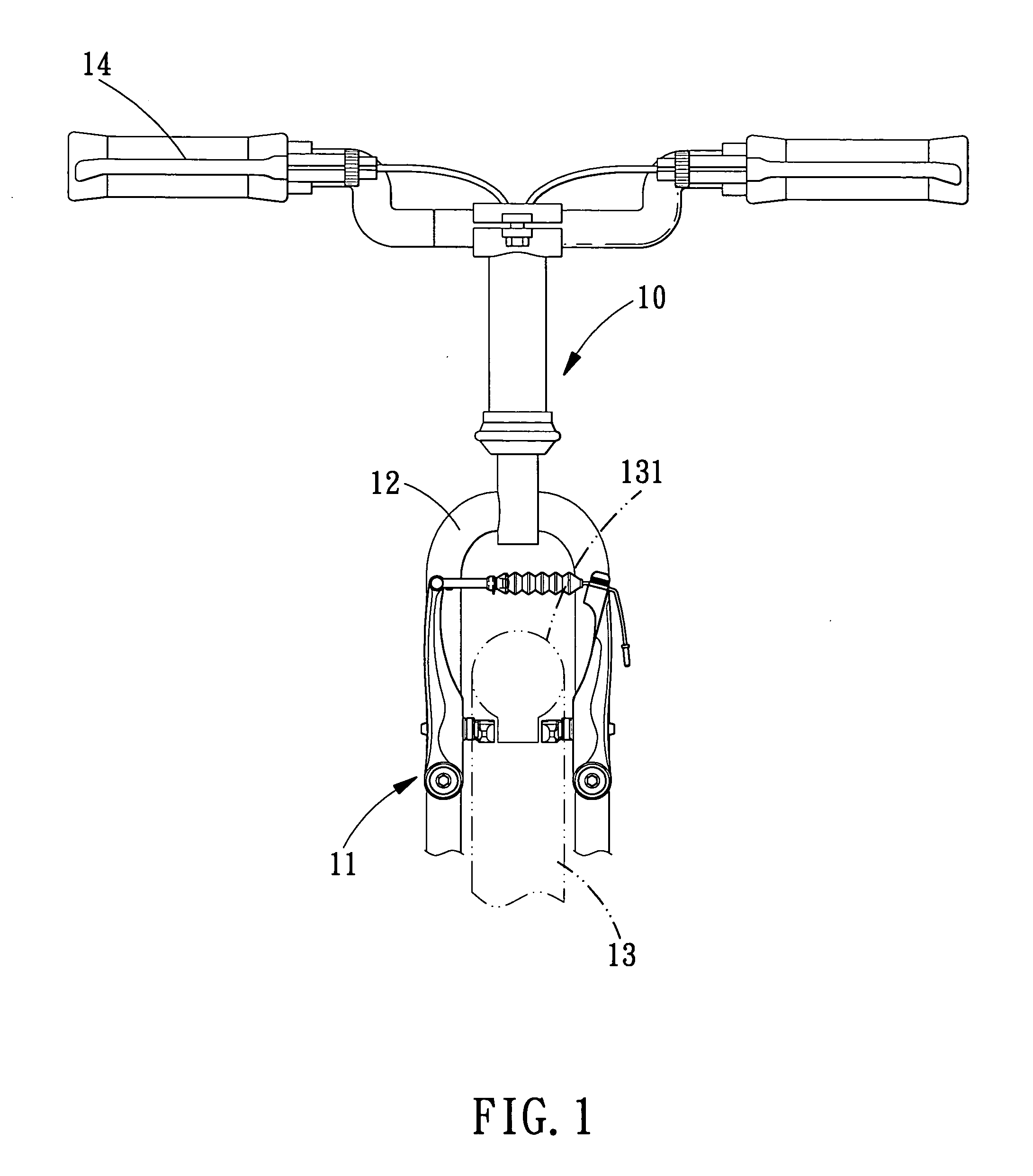
[0022] Referring initially to FIGS. 1 and 2, a front portion of a bicycle 10 is illustrated having a bicycle braking device 11 with a pair of brake shoes 20 according to the present invention. Bicycles and their various components are well-known in the prior art, and thus, bicycle 10 and its various components will not be discussed or illustrated in detail herein, except for the components of bicycle 10 which relate to the braking device 11 in accordance with the present invention. In other words, only bicycle braking device 11 will be discussed and illustrated in detail herein.

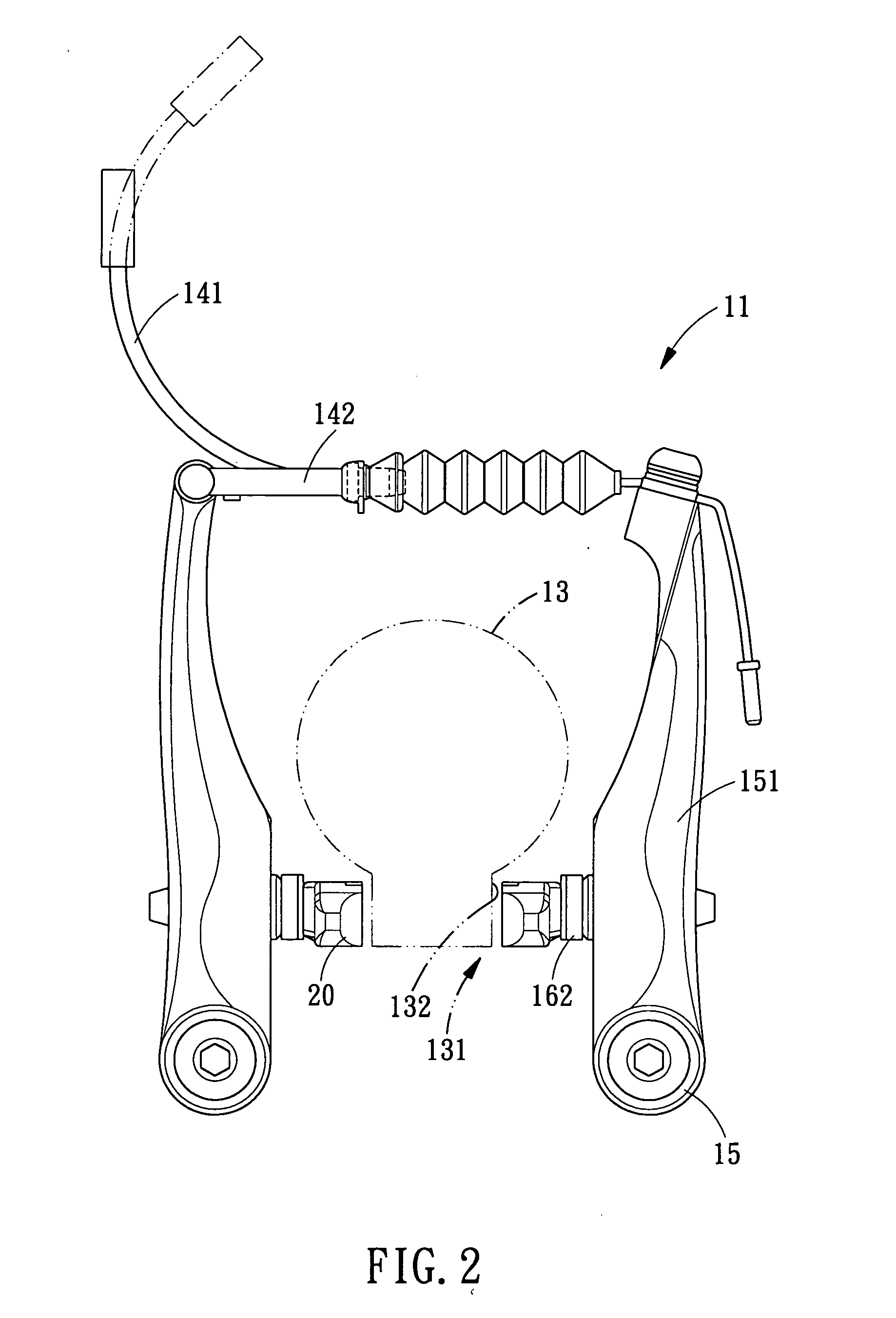
[0023] As seen in FIG. 1, the front braking device 11 is illustrated as being coupled to front fork 12 of bicycle 10 in a relatively conventional manner. Of course, it will be apparent to those skilled in the art from this disclosure that another braking device 11 is preferably coupled to the rear fork of bicycle 10 in a conventional manner.

[0024] As shown in FIGS. 2 and 3, the front braking device 11 is a ...


PUM


Abstract

Bicycle brake shoes are provided for a bicycle braking device. The brake shoes are pressed into contact with a bicycle wheel rim to apply a braking force thereto. The brake shoes are coupled to the bicycle braking device by brake shoe holders. Each brake shoe includes an attachment portion coupled to the brake shoe holder and a rim contacting portion for contacting the side braking surface of the rim. The brake shoes are formed from a polymer that is obtained by cross-linking Nitrile Buna Rubber, Styrene-butadiene rubber with sulfur. The brake shoe is elongated in the rotation direction of the wheel rim and has a braking surface opposite to the braked surface of the rim.

Description

BACKGROUND OF THE INVENTION [0001] 1. Field of the Invention [0002] The present invention relates to brake shoes are formed from a polymer that is obtained by cross-linking Nitrile Buna Rubber, Styrene-butadiene rubber with sulfur, and the polymer is further added with predetermined superaddition, so that said bicycle brake shoe does not excessively wear the rim while maintaining good performance in wet conditions. [0003] 2. Description of the Prior Arts [0004] There are several types of bicycle braking devices on the current market. The types of bicycle braking devices include rim brakes and caliper brake, and the caliper brakes generally includes: a cantilever type, a side pull type, a center pull type. [0005] All these prior art bicycle brakes are equipped with brake shoes typically molded from a rubber that is cross-linked with sulfur. The braking surfaces of the bicycle rim maybe hard and shiny surfaces that have been anodized, or the braking surface can be been ground and then...

Claims


Application Information

Patent Timeline
IPC IPC(8): F16D69/00
CPCB62L1/10F16D65/092F16D69/025F16D2069/004
Inventor LIN, A. P.
Owner LIN A P
Why Eureka
Try Eureka