
Pneumatic tire

a technology of pneumatic tires and blocks, applied in the field of pneumatic tires, can solve the problems of suppressing uneven wear of blocks, and achieve the effects of reducing the force of the ground contact patch on the block when the tire contacts the ground, reducing the force of the ground contact patch, and reducing the friction of the block

Active Publication Date: 2020-02-11
THE YOKOHAMA RUBBER CO LTD
View PDF24 Cites 0 Cited by
  • Summary
  • Abstract
  • Description
  • Claims
  • Application Information

AI Technical Summary

Benefits of technology

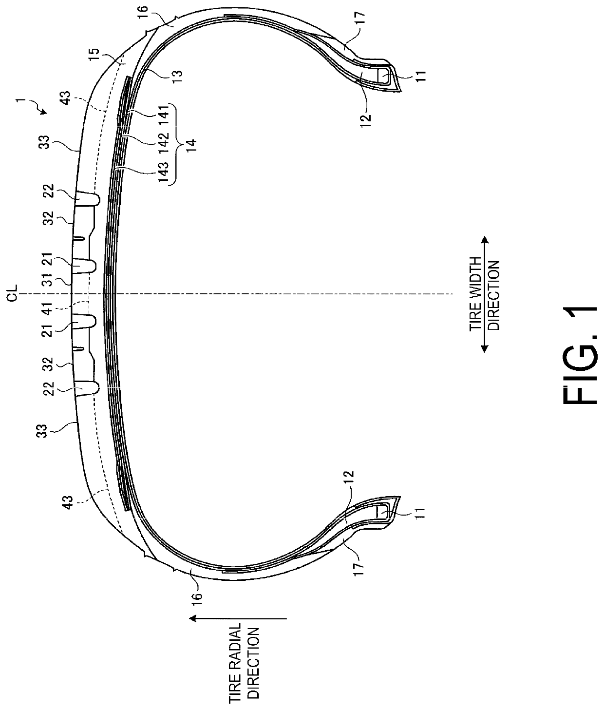
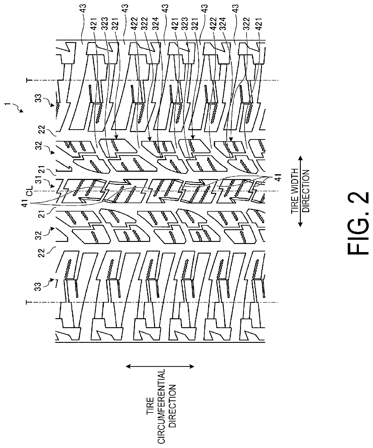
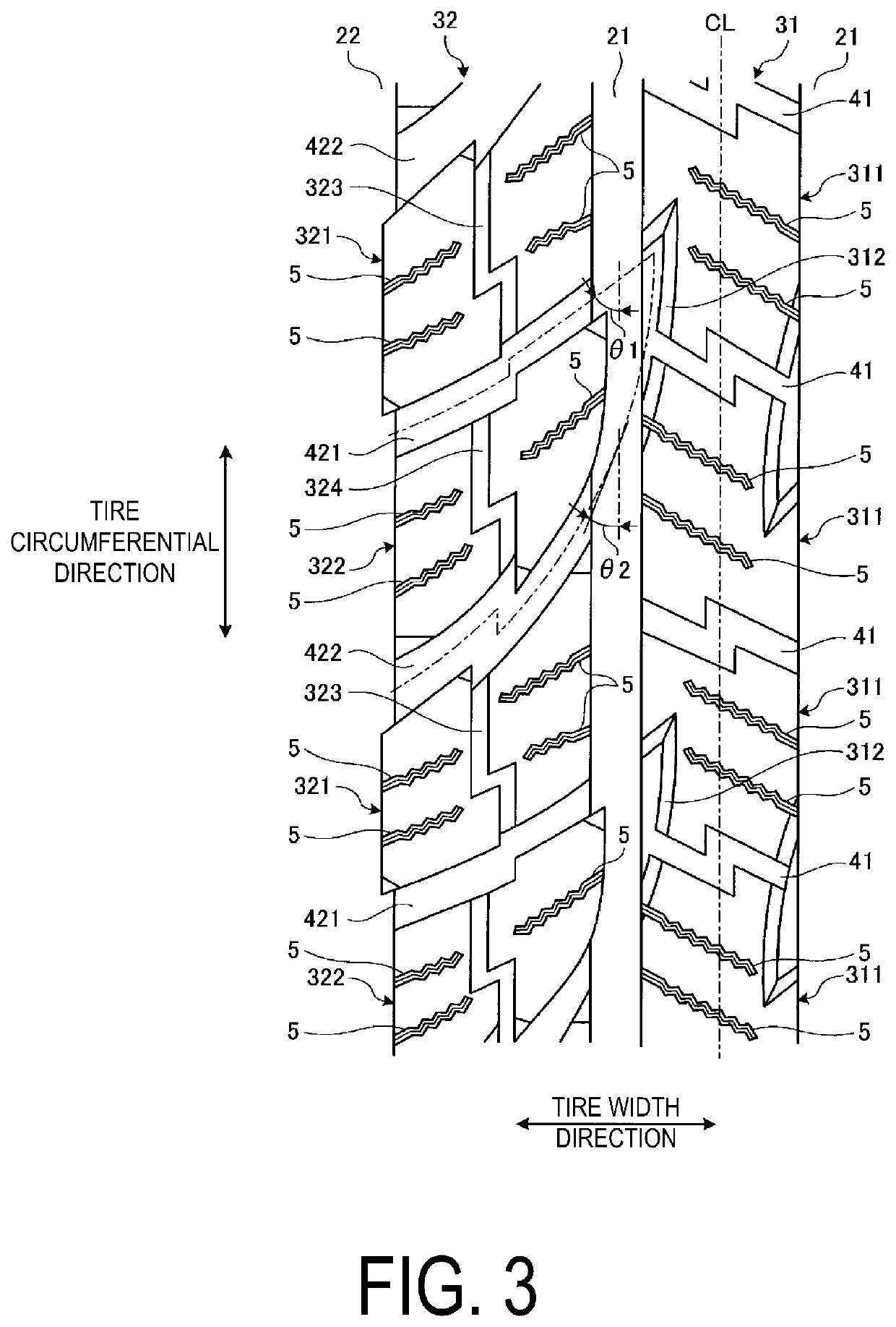
The present technology is about improving the performance of pneumatic tires on snow and resisting uneven wear. It does this by adding a narrow groove in each block of the tire's second land portion. This reduces rigidity in the tire width direction, resulting in lower ground contact patch pressure and less uneven wear of the blocks. The narrow grooves also increase the edge components of the blocks, further enhancing the tire's performance on snow.

Problems solved by technology

However, with configurations utilizing block patterns, there is a problem in that uneven wear of the blocks must be suppressed.

Method used


Image

  • Pneumatic tire
  • Pneumatic tire
  • Pneumatic tire

Examples


modified examples

[0073]FIG. 6 is an explanatory drawing illustrating a modified example of the pneumatic tire depicted in FIG. 2. FIG. 6 is an enlarged view of the second land portion 32.

[0074]In the configuration illustrated in FIG. 2, as illustrated in FIG. 4, the edge portions on the lug grooves 421, 422 sides of the blocks 321, 322 have a step offset in the tire circumferential direction. This step has the opening portions of the circumferential narrow grooves 323, 324 as boundaries. Additionally, the edge portions of opposing blocks 321, 322 have a step offset in the same direction. As a result, lengths in the tire circumferential direction of the portions of the blocks 321, 322 divided by the circumferential narrow grooves 323, 324 are adjusted, and rigidity of the portions of the blocks 321, 322 is made uniform.

[0075]In contrast, in the configuration illustrated in FIG. 6, the edge portion on the lug grooves 421, 422 sides of a first block 321 is stepless and has a flat shape; and the edge po...

examples

[0095]FIG. 7 is a table showing results of performance testing of pneumatic tires according to embodiments of the present technology.

[0096]In the performance testing, a plurality of types of pneumatic test tires were evaluated for (1) performance on snow, (2) uneven wear resistance performance, and (3) noise performance. Each of the test tires had a tire size of 265 / 65R17 112H and was assembled on a on a rim with a rim size of 17×8J. The test tires were inflated to an air pressure of 230 kPa and loaded with the maximum load stipulated by JATMA. The test tires were mounted on all the wheels of a test vehicle, namely, a four wheel drive recreational vehicle (RV) with an engine displacement of 3.5 L.

[0097](1) Evaluation of performance on snow: The test vehicle was driven on a snowy road surface of a snowy road test site, and the braking distance from a traveling speed of 40 km / h was measured. The measurement results were indexed and the index value of the Conventional Example was defin...


PUM


Abstract

A pneumatic tire includes at least four circumferential main grooves extending in the tire circumferential direction; and at least five rows of land portions including a center land portion, a pair of second land portions, and a pair of shoulder land portions, which are defined by the circumferential main grooves. Additionally, at least one row of the second land portions is provided with a plurality of lug grooves penetrating through the second land portion in the tire width direction, and a plurality of blocks defined by the plurality of lug grooves. Moreover, the plurality of blocks include one of the circumferential narrow grooves, respectively, which penetrates through the blocks in the tire circumferential direction.

Description

TECHNICAL FIELD[0001]The present technology relates to a pneumatic tire, and particularly relates to a pneumatic tire with enhanced performance on snow and enhanced uneven wear resistance performance.BACKGROUND ART[0002]With conventional pneumatic tires, performance on snow of a tire is enhanced by utilizing block patterns to increase traction characteristics.[0003]The technology disclosed in Japanese Patent No. 4677408B is a known conventional pneumatic tire that utilizes such a configuration. However, with configurations utilizing block patterns, there is a problem in that uneven wear of the blocks must be suppressed.SUMMARY[0004]The present technology provides a pneumatic tire with enhanced performance on snow and enhanced uneven wear resistance performance.[0005]The pneumatic tire according to the present technology includes at least four circumferential main grooves extending in a tire circumferential direction; and a least five land portions including a center land portion, a ...

Claims


Application Information

Patent Timeline
Patent Type & Authority Patents(United States)
IPC IPC(8): B60C11/11B60C11/03B60C11/13B60C11/12
CPCB60C11/11B60C11/1369B60C11/13B60C11/1384B60C11/12B60C11/1204B60C11/03B60C11/1392B60C2011/0348B60C2011/0369B60C2011/0372B60C2011/129B60C2011/1213B60C2011/0346B60C2011/0358B60C2011/0374
Inventor NISHINO, TOMOHISA
Owner THE YOKOHAMA RUBBER CO LTD
Learn More