
Ceramic RF Filter With Structure for Blocking RF Signal Coupling

a monoblock rf filter and ceramic rf technology, applied in the field of radiofrequency filter, can solve the problems of reducing the filter's capacity to attenuate/reject unwanted frequencies, complex interactions between difficult to predict the interaction of the electric and electromagnetic fields within and around the resonator and the block, etc., to achieve the effect of increasing the length or the size of the block however, and not desirable

Active Publication Date: 2018-03-29
CTS CORP ELKHART
View PDF0 Cites 0 Cited by
  • Summary
  • Abstract
  • Description
  • Claims
  • Application Information

AI Technical Summary

Benefits of technology

The present invention relates to an RF filter for the transmission of an RF signal. The filter includes a block of dielectric material with through-holes and resonators. The first plurality of resonators are located on the block and the second plurality of resonators are located on the block in a relationship to the first plurality of resonators. The second plurality of resonators can block the coupling of the RF signal between certain ones of the first plurality of resonators and selected ones of the first plurality of RF signal input / outputs. The invention provides an RF filter that can effectively block the coupling of RF signals and has improved performance.

Problems solved by technology

A wider bandwidth, however, reduces the filter's capacity to attenuate / reject unwanted frequencies, i.e., frequencies which are known in the art as rejection frequencies.
Interactions of the electric and electromagnetic fields within and around the resonators and the block are complex and difficult to predict.
Increasing the length or size of the block however is not desirable in applications where space is limited on, for example, a customer's motherboard.

Method used


Image

  • Ceramic RF Filter With Structure for Blocking RF Signal Coupling
  • Ceramic RF Filter With Structure for Blocking RF Signal Coupling
  • Ceramic RF Filter With Structure for Blocking RF Signal Coupling

Examples


Embodiment Construction

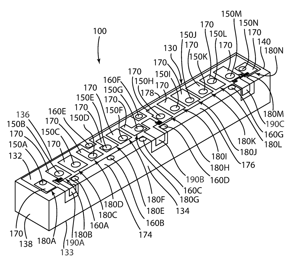
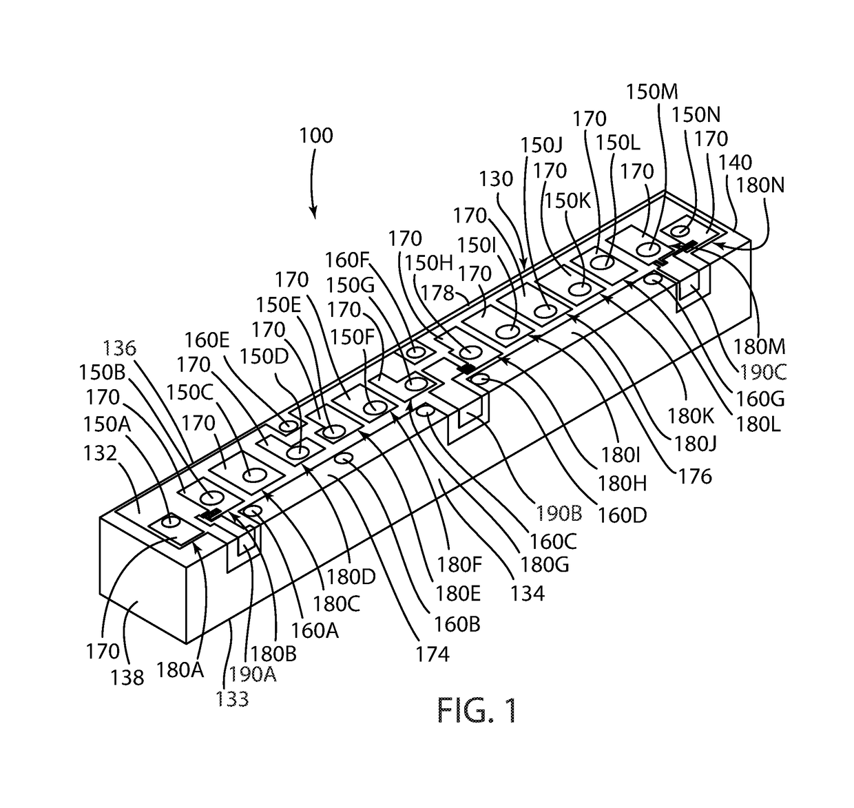
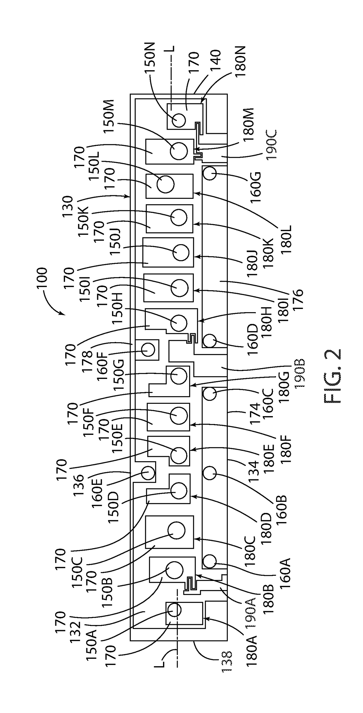
[0030]FIGS. 1, 2, and 3 depict a ceramic monoblock radio-frequency (RF) filter 100, and more specifically a duplexer RF filter, in accordance with the present invention that includes an elongate, parallelepiped (or “box shaped”) solid core or body or monoblock 130 composed of ceramic dielectric material and including three sets of opposing side surfaces: a top longitudinal surface 132, a bottom longitudinal surface 133 opposed, spaced, and parallel to the top surface 132; opposing, spaced apart, and parallel long or longitudinally extending sides or surfaces 134 and 136; and opposed short or transversely extending sides or surfaces 138 and 140. The interface between the sides 134, 136, 138, and 140 define four vertical, parallel, and spaced apart edges extending between the top surface 132 and the bottom surface 133. The core 130 has a length, a width, and a height.

[0031]The core 130 defines a first plurality of generally cylindrically shaped and generally centrally located through-...


PUM


Abstract

A ceramic monoblock RF filter for the transmission of an RF signal comprising a block of dielectric material including opposed top and bottom surfaces, opposed longitudinal side surfaces, and opposed transverse side surfaces. A plurality of spaced apart through-hole resonators extend through the block and terminate in openings in the top and bottom surfaces of the block. A second plurality of grounded RF signal blocking through-holes extend through the block and terminate in respective openings in the top and bottom surfaces of the block. The grounded through-holes are located and positioned in a relationship off-set and on opposite sides of the first plurality of through-hole resonators for blocking the coupling of the RF signal between RF signal input / outputs and selected ones of the first plurality of resonators and also between non-adjacent ones of the first plurality of resonators.

Description

CROSS-REFERENCE TO RELATED APPLICATION[0001]This patent application claims priority and benefit of the filing date of U.S. Provisional Patent Application Ser. No. 62 / 399,018 filed on Sep. 23, 2016, the disclosure and contents of which are expressly incorporated herein in its entirety by reference.TECHNICAL FIELD[0002]This invention relates to a radio-frequency (RF) filter and, more specifically, to a ceramic monoblock RF filter in which structure in the form of grounded through-holes in the filter block unwanted RF signal coupling and provide additional RF signal rejection outside of the bandwidth of the RF filter without an increase in the length or size of the filter.BACKGROUND OF THE INVENTION[0003]Ceramic monoblock radio-frequency (RF) filters provide for the attenuation / rejection of RF signals with frequencies outside of a particular frequency range or band and little rejection / attenuation to RF signals with frequencies within a particular range or band of interest.[0004]These ...

Claims


Application Information

Patent Timeline
IPC IPC(8): H01P1/205H01P1/213
CPCH01P1/2056H01P1/2136
Inventor ROGOZINE, ALEXANDRE
Owner CTS CORP ELKHART
Features
  • Generate Ideas
  • Intellectual Property
  • Life Sciences
  • Materials
  • Tech Scout
  • Unparalleled Data Quality
  • Higher Quality Content
  • 60% Fewer Hallucinations
Learn More