Video matrix controller

Active Publication Date: 2018-03-29
ATEN INT CO
View PDF1 Cites 3 Cited by
  • Summary
  • Abstract
  • Description
  • Claims
  • Application Information

AI Technical Summary

Benefits of technology

The present invention is a video matrix control device that improves upon existing technologies. The device includes multiple receiving modules, a matrix switch module, and transmission modules. Each receiving module has first port interfaces and a transceiver element to convert image data into signals. These signals are then transmitted to the matrix switch module. The transmission module has second port interfaces and a transceiver element to receive the signals from the matrix switch module. The device also includes a streaming module to capture images from the transmission module and display them on a computer. In summary, the video matrix control device improves image processing and control over external displays.

Problems solved by technology

As a result, the wiring is complex, the wire cost is increased, and the size of the control device is increased.
It also increases repair complexity and cost.
Also, one-to-one wiring cannot support cross-screen picture-in-picture (PIP) display and other extended applications.
In other words, conventional TV wall mode cannot achieve cross-screen PIP display.

Method used


Image

  • Video matrix controller
  • Video matrix controller
  • Video matrix controller

Examples


Embodiment Construction

[0015]Preferred embodiments of the present invention are described below. These description explains implementation details of the embodiments, to allow the reader to understand the embodiments. However, those skilled in the relevant art would appreciate that the invention may be implemented without some of the details. Further, for purposes of clarity and brevity, well known structures and functions are not described in detail. The terminology used in the following descriptions should be given the broadest reasonable interpretation, even when they are used to describe details of the embodiments.

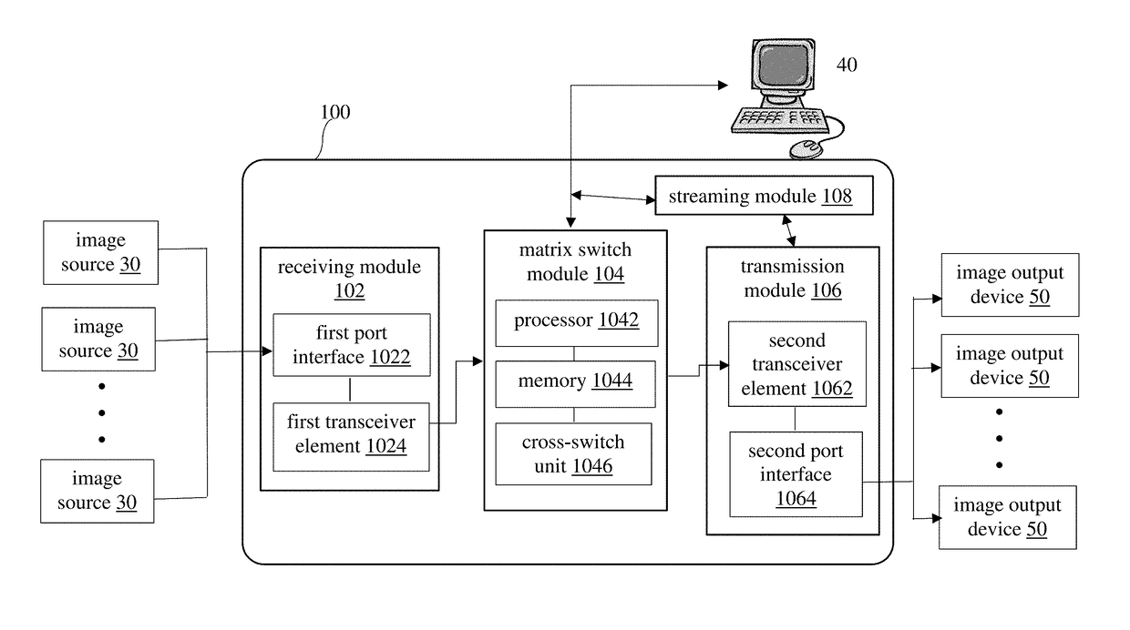
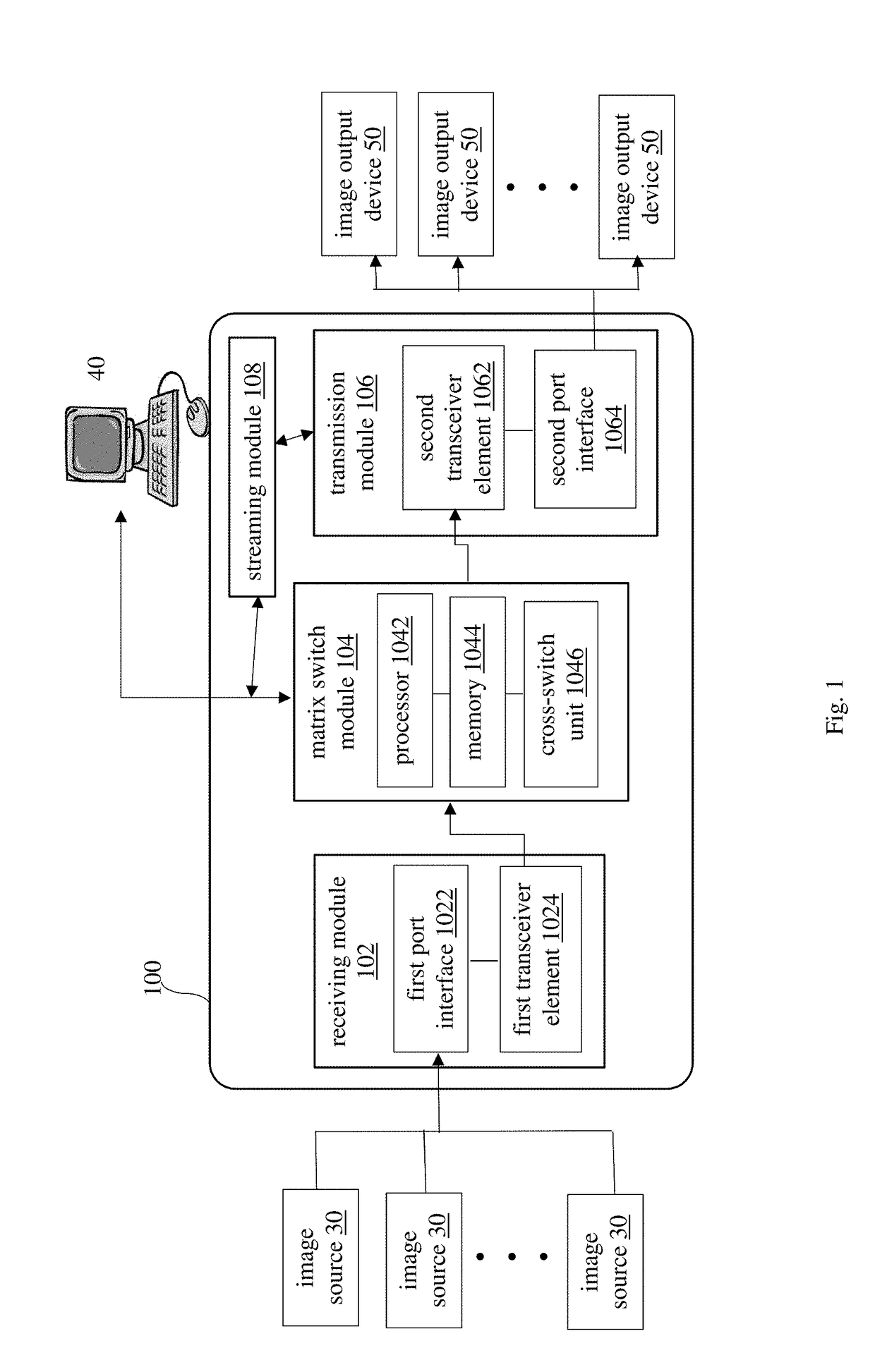
[0016]Refer to FIG. 1, which is a block diagram showing the structure of a video matrix control device 100 (referred to as device 100) according to a first embodiment. In practical applications, the device 100 is disposed between multiple image sources 30 and multiple image output devices 50 (i.e. the video matrix apparatus). In other words, the device 100 can be coupled to multiple differen...


PUM


Abstract

A video matrix controller, including a receiving module, a matrix switch module and a transmission module. The matrix switch module is coupled between the receiving module and the transmission module. The receiving module includes a first port interface and a first transceiver. The first port interface receives image data and converts it to a signal, and transmits it to the first transceiver. The transmission module includes a second transceiver and a second port interface. The signal is transmitted from the first transceiver to the matrix switch module. The second transceiver receives the signal, and the second port interface converts the signal to image data and transmits it to a corresponding external display device.

Description

BACKGROUND OF THE INVENTIONField of the Invention[0001]This invention relates to a video controller, and in particular, it relates to a video matrix controller.Description of Related Art[0002]With the rapid development of new technologies, information technology is changing people's lifestyle. Today, various types of video apparatus apply technology, network and their combination to make image display technologies more diverse, and image resolution is also greatly improved, so that image display methods help consumer to change their visual impression of products.[0003]Matrix display devices are widely used for outdoor display such as on the streets. They use multiple display devices arranged in X*X or X*Y video matrices (also called TV walls). The display devices can receive the same image, or, an original image can be divided into X*X or X*Y sub-images, and the sub-images are transmitted to the corresponding display device in a predetermined correspondence order. This way, although...

Claims


Application Information

Patent Timeline
IPC IPC(8): H04N5/268
CPCH04N5/268
Inventor CHEN, YI-JENHUANG, SHIH-JUNG
Owner ATEN INT CO
Why Eureka
Try Eureka