Substrate polishing apparatus
- Summary
- Abstract
- Description
- Claims
- Application Information
AI Technical Summary
Benefits of technology
Problems solved by technology
Method used
Image

Examples
first embodiment
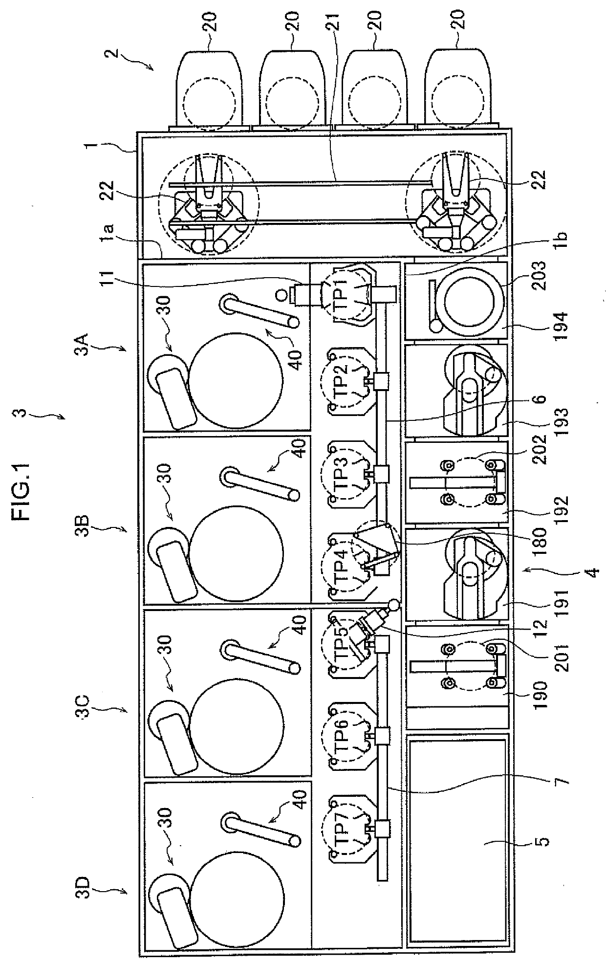
[0048]FIG. 1 is a schematic plan view of a substrate processing apparatus having substrate polishing apparatuses 3A to 3D according to a first embodiment. As shown in FIG. 1, the substrate processing apparatus includes a housing 1 having a substantially rectangular shape, and the inside of the housing 1 is partitioned into a load / unload module 2, a polisher 3, and a cleaner 4 by partition walls 1a and 1b. Each of the load / unload module 2, the polisher 3, and the cleaner 4 is individually assembled and individually exhausted. A substrate is polished in the polisher 3. The polished substrate is cleaned and dried in the cleaner 4. Further, the substrate processing apparatus has a controller 5 that controls a substrate processing operation.
[0049]The load / unload module 2 includes two or more (four in the present embodiment) front loaders 20, in each of which a substrate cassette where many substrates (for example, semiconductor wafers) are stocked is mounted. The front loaders 20 are dis...
second embodiment
[0112]In the first embodiment described above, the force sensors 46a to 46c detect forces in three axis directions. On the other hand, in a second embodiment described below, force sensors that detect a force in the vertical direction (z direction) are used. Although a schematic side view of a substrate polishing apparatus 3A according to the present embodiment is nearly the same as that in FIG. 2, an example in which four force sensors 46h to 46i are used will be described. Hereinafter, differences from the first embodiment will be mainly described.
[0113]FIG. 8A is a schematic cross-sectional view of a substrate polishing apparatus 3A′ passing through force sensors 46h to 46k, which is an example of a second embodiment. When the center of the dresser shaft 42 is defined as the origin, coordinates where the force sensors 46h to 46k are disposed are (Rxh, 0), (−Rxi, 0), (0, Ryj), and (0, −Ryk), respectively. Here, Rxh=Rxi may be established and Ryj=Rhk may be established.
[0114]FIG. 8...
third embodiment
[0124]A third embodiment described below makes it possible to detect an abnormality of a force sensor.
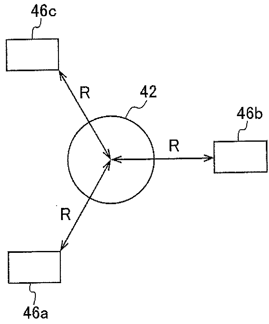
[0125]A substrate polishing apparatus 3A according to the present embodiment has the force sensors 46a to 46c that detect forces in three axis directions in the same manner as in the first embodiment.
[0126]Therefore, in the same manner as described in the first embodiment, the pad dressing force calculator 52 can calculate Fx, Fy, |F|, and θ based on output information pieces Fxa′ to Fxc′ and Fya′ to Fyc′ related to the horizontal direction.
[0127]Further, in the same manner as described in the second embodiment, the pad dressing force calculator 52 can calculate Fx, Fy, |F|, and θ based on output information pieces Fza′ to Fzc′ related to the vertical direction.
[0128]Then, the determiner 56 compares the magnitude of force |F| based on output information related to the horizontal direction with the magnitude of force |F| based on output information related to the vertical direction. ...
PUM
 Abstract
Description
Claims
Application Information
 - R&D Engineer
- R&D Manager
- IP Professional
- Industry Leading Data Capabilities
- Powerful AI technology
- Patent DNA Extraction
Browse by: Latest US Patents, China's latest patents, Technical Efficacy Thesaurus, Application Domain, Technology Topic.
© 2024 PatSnap. All rights reserved.Legal|Privacy policy|Modern Slavery Act Transparency Statement|Sitemap