Current Measuring Equipment and Methods

a technology of current measuring equipment and methods, applied in the direction of measurement devices, instruments, voltage/current isolation, etc., can solve the problem of arranging all the elements of measuring equipment in said locations and causing drawbacks

Active Publication Date: 2018-04-05
LUMIKER APLICACIONES TECHCAS SL
View PDF7 Cites 5 Cited by
  • Summary
  • Abstract
  • Description
  • Claims
  • Application Information

AI Technical Summary

Benefits of technology

[0008]The standard single-mode fiber used for joining the interrogator with the sensing portion can change the characteristics of the light signal emitted from the emitter, for example, in the polarization thereof. Said intermediate fiber can modify the polarization of light due to different aspects such as the temperature of said fiber, the vibrations it suffered, etc. The action of emitting sets of at least two polarized light pulses, said pulses being polarized with a specific degree difference, means that the measuring equipment can compensate for the alterations produced by the intermediate fiber.
[0009]Since...

Problems solved by technology

When the conductor, the sensing of which is to be achieved is arranged in a remote location, arranging all the elements making up the mea...

Method used


Image

  • Current Measuring Equipment and Methods
  • Current Measuring Equipment and Methods
  • Current Measuring Equipment and Methods

Examples


Embodiment Construction

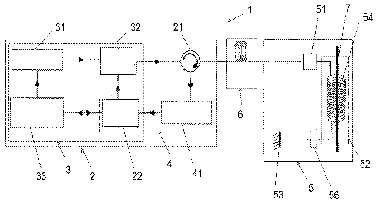
[0020]FIG. 1 shows a first embodiment of the current measuring equipment based on optical fiber 1 for measuring the current circulating through a conductor 7.

[0021]The current measuring equipment 1 comprises an interrogator 2 with an emitter 3 and a receiver 4 and a sensing portion 5 close to the conductor 7. The interrogator 2 and the sensing portion 5 are configured for being connected through a standard single-mode intermediate fiber 6.

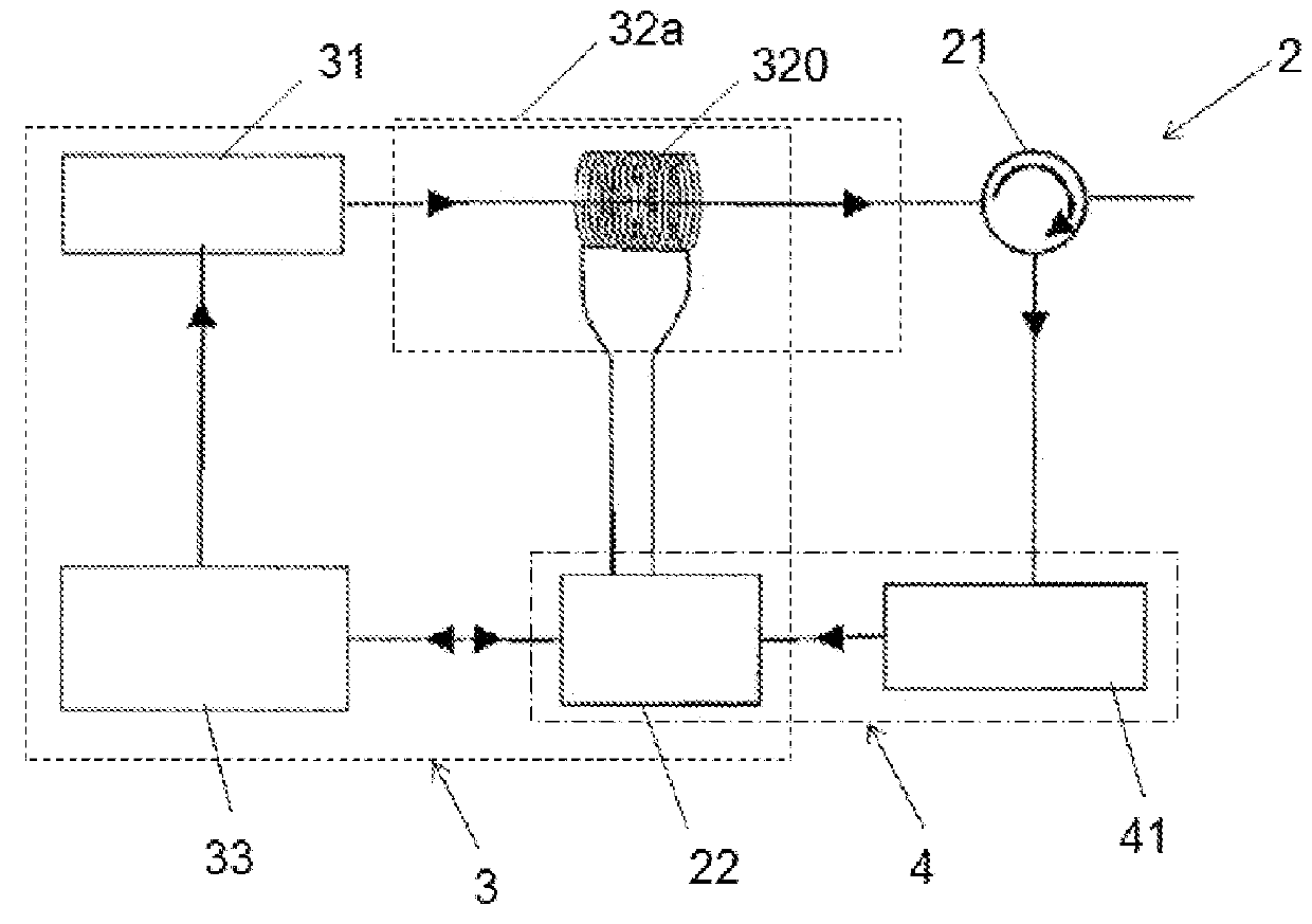
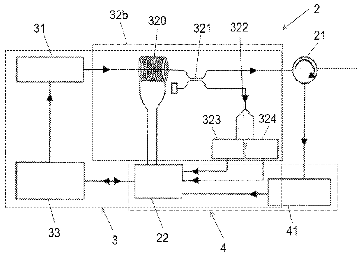
[0022]In this embodiment, the interrogator 2 comprises a rotator 21 the function of which consists of coupling the signal emitted by the emitter 3 to the intermediate fiber 6 and coupling the modified signal in the sensing portion 5 from the intermediate fiber 6 to the receiver 4.

[0023]The current measuring equipment 1 is designed such that the influence of the standard single-mode intermediate fiber 6 can be eliminated. The current measuring equipment 1 can therefore use standard single-mode fibers already installed for other uses and the intermed...


PUM


Abstract

Optical fiber based current measuring equipment for measuring the current circulating through a conductor. The equipment includes an interrogator having a light emitter and a light receiver, and a sensing portion close to the conductor, the interrogator and the sensing portion being connected through at least one standard single-mode intermediate fiber. The light emitter of the interrogator is configured to emit sets of at least two polarized light pulses to the sensing portion, the pulses being polarized with a specific degree difference, and the light receiver (4) is configured to determine the current circulating through the conductor depending on the pulses it receives in return from the sensing portion. A method for measuring the current circulating through a conductor with the use of an optical fiber based current measuring equipment is also provided.

Description

CROSS-REFERENCE TO RELATED APPLICATIONS[0001]This application relates to and claims the benefit and priority to International Application No. PCT / EP2016 / 063261, filed Jun. 10, 2016, which claims the benefit and priority to European Application No. 15382303.4, filed Jun. 10, 2015, each of which is incorporated by reference herein in its entirety . . . .FIELD[0002]The present invention relates to a current measuring equipment based on optical fiber for measuring the current circulating through a conductor, and to a method for measuring the current circulating through a conductor with a current measuring equipment based on optical fiber.BACKGROUND[0003]Sensors based on optical fiber for measuring the current circulating through a conductor are known. Said sensors work according to the Faraday Effect, i.e., the magnetic field generated by the current circulating through the conductor causes a rotation in the polarization of light circulating through the optical fiber arranged around the...

Claims


Application Information

Patent Timeline
IPC IPC(8): G01R15/24G01R19/00
CPCG01R15/246G01R19/0092G01R33/0322
Inventor BENGOECHEA DE LA LLERA, FRANCISCO JAVIERGARCIA CARROMERO, MYRIAM CONSUELO
Owner LUMIKER APLICACIONES TECHCAS SL
Why Eureka
Try Eureka