Insulating molding for a battery cell

a battery cell and insulation molding technology, applied in the direction of batteries, cell components, sustainable manufacturing/processing, etc., can solve the problems of high clamping force, substantial loss of battery cell capacity, and depletion of storage capacity, so as to achieve the optimal compensation of battery cell distension and the effect of less housing material and great distension

Active Publication Date: 2018-04-05
ROBERT BOSCH GMBH
View PDF5 Cites 2 Cited by
  • Summary
  • Abstract
  • Description
  • Claims
  • Application Information

AI Technical Summary

Benefits of technology

[0024]In a particularly preferred form of embodiment, the depression is located in a central zone of the at least one molding sidewall, which is circumferentially enclosed by an edge zone of the at least one molding sidewall. This is advantageous, in that a battery cell in the central zone of the electrode assembly, comprising the electrodes and at least one separator, undergoes the greatest distension. The housing of the battery cell thus shows the greatest expansion in a central zone of the battery cell sidewall. The insulating molding incorporating the depression in a central zone is thus located exactly at the position of the greatest expansion of the battery cell, thus permitting the optimum compensation of the distension of the battery cell. Accordingly, no additional forces are applied to the battery cell as a result of distension.
[0025]In a further form of embodiment, the insulating molding is configured as a housing for at least one battery cell. Advantageously, in this manner, less housing material is required, thereby saving weight and, moreover, reducing material and production costs for the battery cell. It is further advantageous that the insulating molding is thus applied directly to the deformable components of the battery cell, and is not separated from the latter by a battery cell housing.
[0026]In an advantageous form of embodiment, the insulating molding is comprised of a plastic. Advantageously, plastic components can be manufactured in a very simple and cost-effective manner, and moreover are easily recyclable. In a particularly advantageous form of embodiment, the insulating molding is comprised of a thermoplastic material, for example a polyamide, a polyethylene, a polypropylene, a polyethylene terephthalate or a polyvinyl chloride, or mixtures thereof. Advantageously, these materials have very good welding properties.
[0027]Polyolefins are flexible, and have a high degree of mechanical and chemical stability. Of these, for example, polyethylene is characterized by high toughness, low water absorption and low water vapor permeability, shows good resistance to chemicals and is moreover easy to process and cost-effective. Polypropylene is characterized by low water absorption, is chemical-resistant, electrically-insulating, easy to process and cost-effective. Polyamide is characterized by high strength, high resistance to chemicals and weathering, and a limited tendency to stress crack formation. Polyvinyl chloride is chemical-resistant, has a high strength, and is cost-effective. Polyethylene terephthalates have a high rupture strength and temperature stability.
[0028]In one form of embodiment, the insulating molding is produced by an injection-molding process. By means of an injection-molding process, for example, plastic components with a complex geometry can be produced with high accuracy in short cycle times. Injection-molding processes are highly cost-effective methods, particularly for the production of large component numbers.

Problems solved by technology

This can lead to a depletion of storage capacity, and thus to the premature ageing of the battery cell which, in turn, is associated with a substantial loss of capacity of the battery cell.
The frequently very high clamping forces thus generated are associated with very high loading, and thus, for example, with a depletion in the porosity of the separator.
Moreover, localized overloading occurs on the electrodes, with the formation, for example, of porous dendritic lithium deposits.
This generally results in an internal short-circuit.
As a result, in turn, the clamping force which is applied to the battery cells for the mechanical clamping thereof, for the purposes of mechanical fixing, can be limited, such that a reduced load is applied to the battery cells.

Method used


Image

  • Insulating molding for a battery cell
  • Insulating molding for a battery cell
  • Insulating molding for a battery cell

Examples


Embodiment Construction

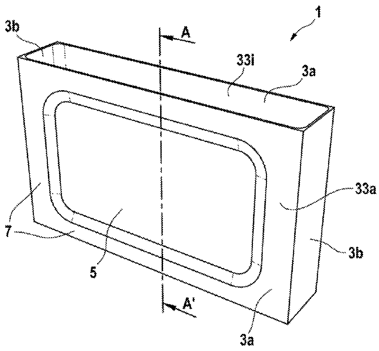
[0040]FIG. 1 shows a first form of embodiment of an insulating molding 1 for at least one housing of a battery cell. The insulating molding 1 comprises two long molding sidewalls 3a and two short molding sidewalls 3b, which are configured with a full-surface design. The long molding sidewalls 3a each comprise an outer side 33a and an inner side 33i. The insulating molding 1 moreover comprises a molding base, which is not visible in FIG. 1. Alternatively, the insulating molding 1 incorporates no molding base. As a further alternative, the insulating molding 1 comprises an unrepresented molding top cover. The insulating molding 1, on the long molding sidewall 3a, incorporates a depression 5, which is configured in the form of a reduced wall thickness in the long molding sidewall 3a. In FIG. 1, only the depression 5 in one of the long molding sidewalls 3a is visible. In FIG. 1, the reduction in the wall thickness of the long molding sidewall 3a is configured on the outer side 33a of th...


PUM

PropertyMeasurementUnit
thicknessaaaaaaaaaa
sizesaaaaaaaaaa
chemical energyaaaaaaaaaa

Abstract

An insulating molding (1) for a housing of at least one battery cell is disclosed, specifically for a housing of at least one lithium-ion battery cell, wherein, on at least one molding sidewall (3a, 3b) of the insulating molding (1), a depression (5) is configured, which is constituted by means of a reduced wall thickness, in order to reduce the force acting on the battery cell.

Description

BACKGROUND OF THE INVENTION[0001]The present invention relates to an insulating molding for a housing of at least one battery cell, to a battery cell, specifically a lithium-ion battery cell, and to a battery.[0002]A battery cell is an electrochemical energy store which, upon the discharging thereof, converts stored chemical energy into electrical energy by an electrochemical reaction. It transpires that, in future, whether in stationary applications such as wind turbines, in motor vehicles which are configured as hybrid or electric vehicles, and in electronic devices, new battery systems will be employed which will be subject to very stringent requirements, with respect to reliability, safety, performance capability and service life.[0003]On the grounds of their high energy density, lithium-ion batteries are specifically employed as energy stores for electrically-powered motor vehicles.[0004]Battery cells, specifically lithium-ion battery cells, are configured, for example, with an...

Claims


Application Information

Patent Timeline
Patent Type & Authority Applications(United States)
IPC IPC(8): H01M2/04H01M2/02H01M10/0525H01M50/202H01M50/227H01M50/242
CPCH01M2/0417H01M2/0217H01M10/0525B29D24/00B29C45/0001H01M2220/20H01M50/202H01M50/227H01M50/242Y02E60/10H01M50/103Y02P70/50H01M50/154
Inventor STRIEGEL, KAI-ULIGERLACH, MARTINKRETSCHMAR, THOMASKEGEL, TIMO
Owner ROBERT BOSCH GMBH
Why Eureka
Try Eureka