
Tread Base for Treadmill

Inactive Publication Date: 2018-04-26
LEE YIN HSUAN
View PDF43 Cites 39 Cited by
  • Summary
  • Abstract
  • Description
  • Claims
  • Application Information

AI Technical Summary

Benefits of technology

The present invention is a tread base for treadmill that has sliding tracks for the movable sliding rollers of the running belt. This improves the stability of the running belt, distributing the impact force to the sliding tracks, preventing damaging the slats of the belt and improving its lifespan. Additionally, it simplifies the fabrication and installation process of the movable sliding rollers and sliding tracks, reducing labor and fabrication costs.

Problems solved by technology

1. The running belt is comprised of a plurality of slat components; when the user is running on the running belt, the left and right bearing support frames supports the opposing left and right sides of the running belt, however, a large part of each slat component is suspended in the open air without support, and thus, the slat components can break easily upon a heavy impact force, causing accidents.
2. The bearings (non-sliding rollers) at the opposing left and right sides of the tread base frame unit are rotatable but not movable with the running belt, unable to enhance the moving smoothness of the running belt.
3. The left and right bearing support frames must be precisely processed to provide precision bearing holes for the mounting of respective bearings; if the machining tolerances of the bearing holes are slightly different, the sliding smoothness of the running belt can be reduced, leading to a defective product; the machining of the bearing holes and the installation of the bearings are complicated and need much labor and time, greatly increasing the manufacturing cost of the treadmill.

Method used


Image

  • Tread Base for Treadmill
  • Tread Base for Treadmill
  • Tread Base for Treadmill

Examples


Embodiment Construction

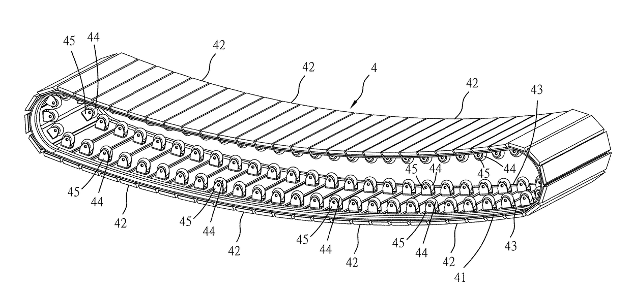
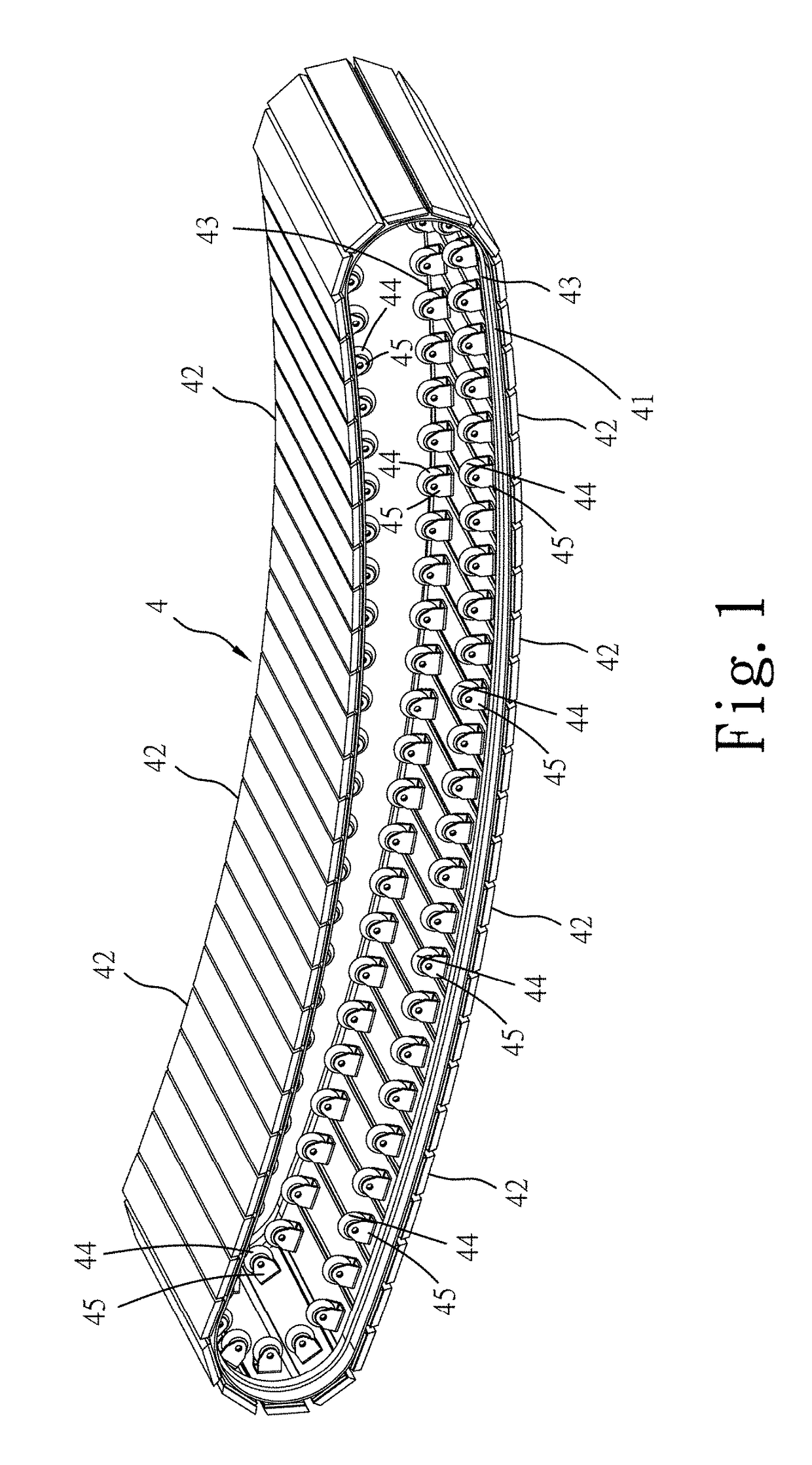
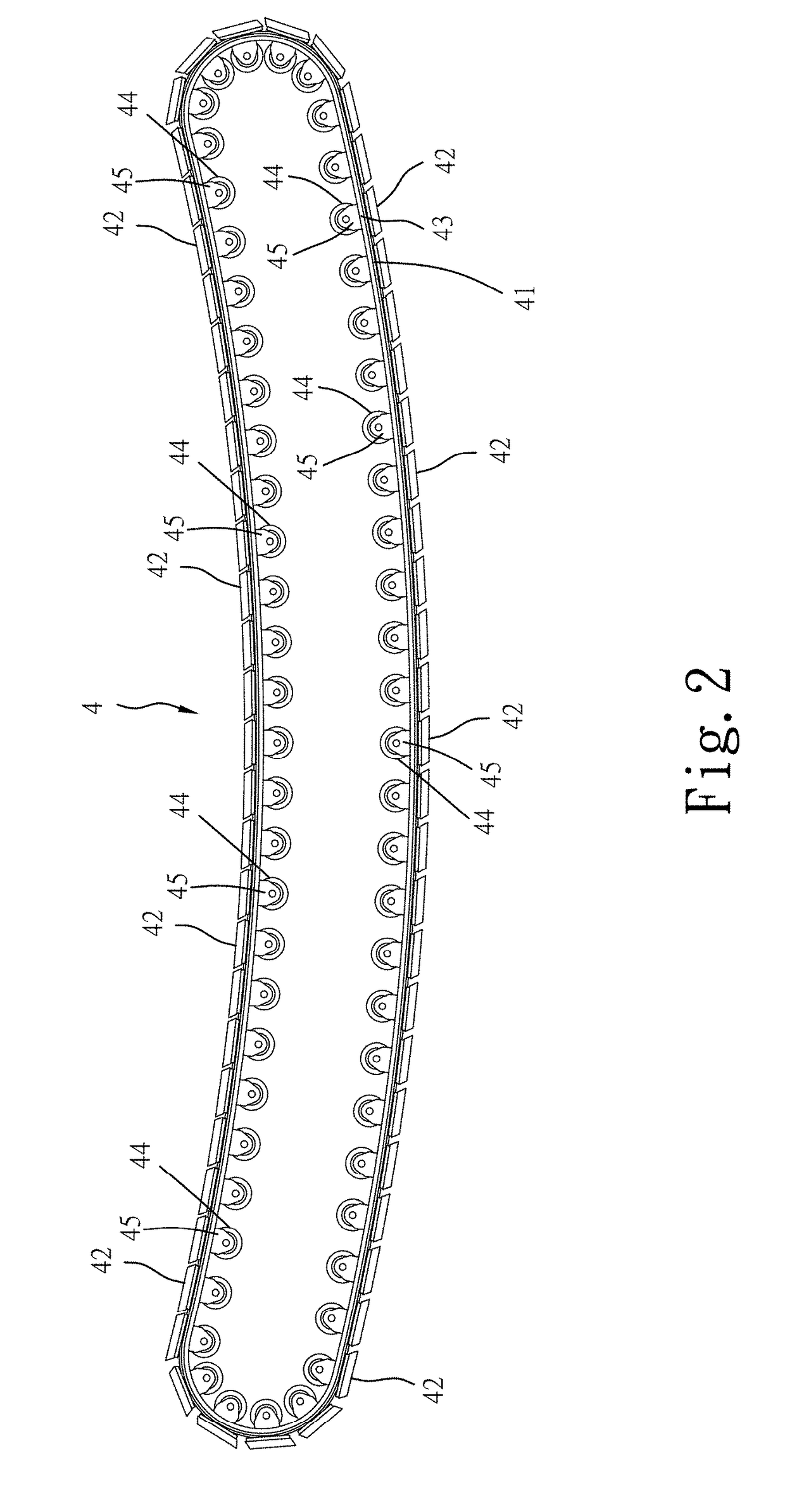
[0019]Referring to FIGS. 1-8, a tread base for treadmill in accordance with the present invention is shown. The tread base comprises:

[0020]a tread base frame unit 1, comprising a main tread base frame 10 (see FIG. 3 and FIG. 4) for holding a front belt wheel set 2 and a rear belt wheel set 3 respectively at opposing front and rear sides thereof, a left bracket 12 and a right bracket 13 respectively affixed to opposing left and right sides of the main tread base frame 10 with fastening means or by welding;

[0021]a front belt wheel set 2 comprising a front wheel axle 21 (see FIG. 3 and FIG. 4) transversely pivotally mounted in the front side of the main tread base frame 10 and two front belt wheels 22 respectively mounted at opposing left and right ends of the front wheel axle 21;

[0022]a rear belt wheel set 3 comprising a rear wheel axle 31 (see FIG. 3 and FIG. 4) transversely pivotally mounted in the rear side of the main tread base frame 10 and two rear belt wheels 32 respectively mo...


PUM


Abstract

A tread base includes a tread base frame unit with front and rear belt wheel sets arranged at opposing front and rear sides thereof, and an endless running belt mounted around the front and rear belt wheel sets and having slats transversely arranged on the outer perimeter thereof in a parallel manner. The running belt includes a plurality of movable sliding rollers respectively mounted at the opposing left and right ends of the slats. The tread base frame unit includes two smoothly arched sliding tracks longitudinally arranged in parallel for supporting and guiding the movable sliding rollers of the running belt to enhance the moving stability of the running belt, preventing breaking of the slats of the running belt, avoiding danger and prolonging the lifespan of the tread base.

Description

BACKGROUND OF THE INVENTION1. Field of the Invention[0001]The present invention relates to treadmill technology and more particularly, to a tread base for treadmill, which has two sliding tracks arranged on a tread base frame unit for supporting and guiding the movement of a movable sliding roller-equipped running belt to enhance the moving stability of the running belt, preventing breaking of slat components of the running belt and prolonging the lifespan of the tread base.2. Description of the Related Art[0002]US2012 / 0010053A1 discloses a manually operated treadmill, which includes a treadmill frame having a front end and a rear end opposite the front end, a front shaft rotatably coupled to the treadmill frame at the front end, a rear shaft rotatably coupled to the treadmill frame at the rear end, and a running belt including a curved running surface upon which a user of the treadmill may run. The running belt is disposed about the front and rear shafts such that force generated b...

Claims


Application Information

Patent Timeline
IPC IPC(8): A63B22/02
CPCA63B22/0285A63B22/02A63B2022/206
Inventor LEE, YIN-HSUAN
Owner LEE YIN HSUAN
Learn More