Conductive member
a technology of conductive components and tubular conductors, which is applied in the direction of braided wire conductors, electrical devices, and permanent deformation-induced connections, can solve the problems of increasing the number of man-hours, increasing the manufacturing cost, and not being able to route the terminal end of tubular conductors to the device, so as to suppress the increase in manufacturing costs and prevent the entry of water
- Summary
- Abstract
- Description
- Claims
- Application Information
AI Technical Summary
Benefits of technology
Problems solved by technology
Method used
Image
Examples
embodiment 1
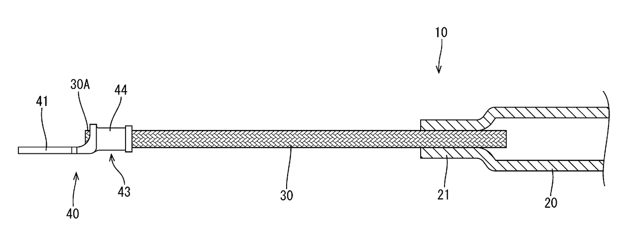
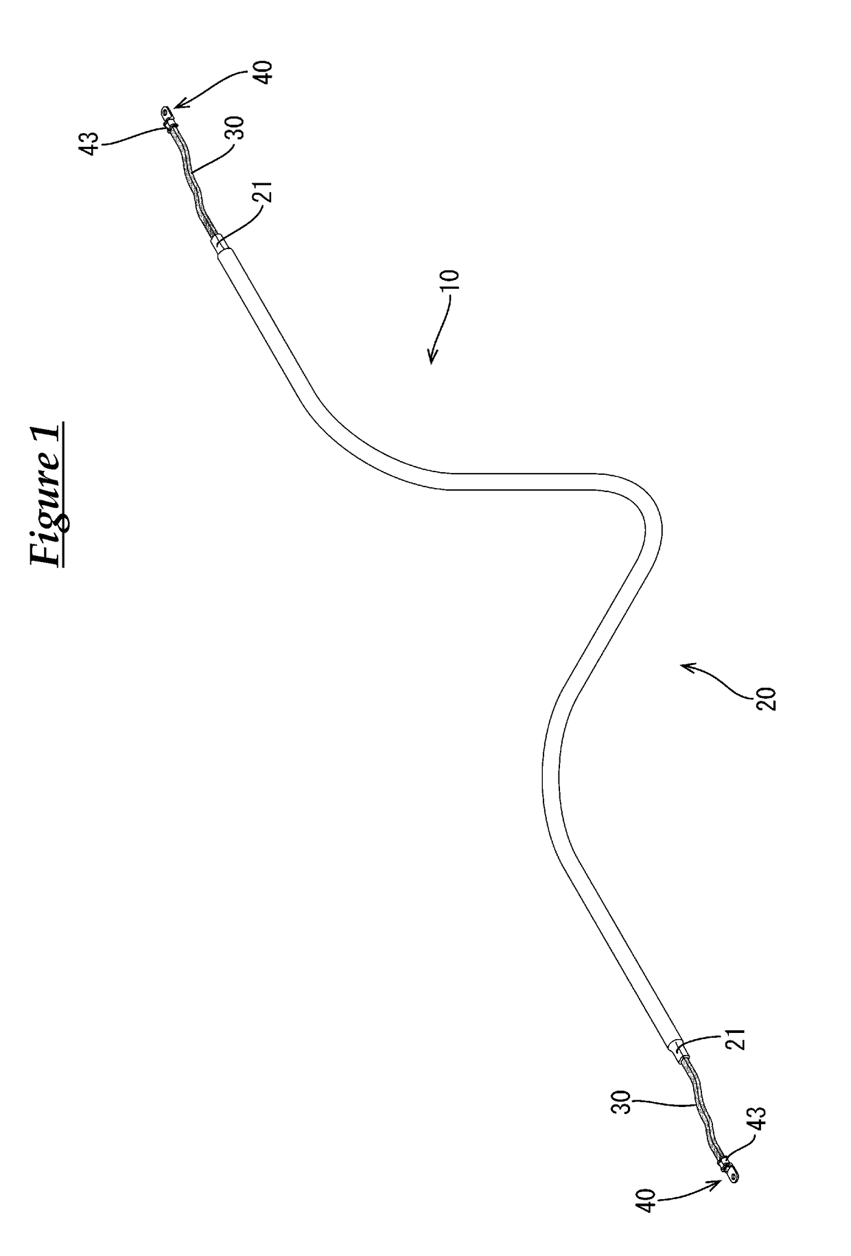
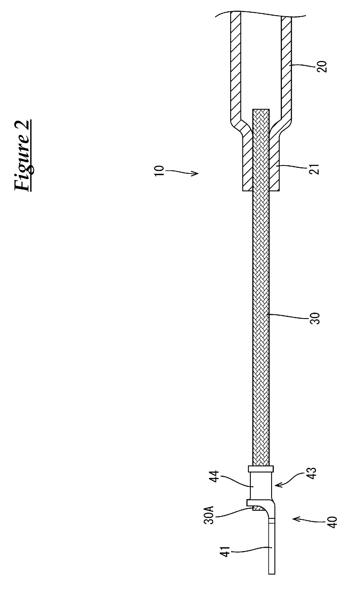
[0036]Embodiment 1 will be described with reference to FIGS. 1 to 4.
[0037]The present embodiment is directed at a signal-carrying conductive member 10 that connects a battery (not shown) disposed at the rear of a vehicle to devices (not shown) installed in an engine room provided at the front of the vehicle, and the routing path of the conductive member 10 between the battery and the engine room is underneath the floor of the vehicle.
[0038]As shown in FIGS. 1 and 4, the conductive member 10 includes a pipe member (an example of a “tubular conductor”) 20 extending in the front-rear direction from the engine room to the rear of the vehicle underneath the floor of the vehicle, flexible braided wires (an example of a “flexible conductor”) 30 that are respectively connected to front and rear ends of the pipe member 20, round terminals (an example of a “terminal”) 40 that are connected to the respective braided wires 30 on the side opposite to the side where the pipe member 20 is connecte...
embodiment 2
[0066]Next, Embodiment 2 will be described with reference to FIG. 5.
[0067]A conductive member 110 according to Embodiment 2 is formed by changing the region covered by the heat-shrinkable tube 50 of Embodiment 1, and covering the end 30A of the braided wire 30 with solder (an example of a “sealant”) 60. The description of the components, function, and effect that are common to Embodiment 1 is redundant and therefore has been omitted. In addition, components that are the same as those of Embodiment 1 are denoted by the same reference numerals.
[0068]As shown in FIG. 5, the heat-shrinkable tube 150 of Embodiment 2 has a configuration in which the crimped portion 43 of the round terminal 40 is covered, up to approximately the central portion in the front-rear direction. That is, the heat-shrinkable tube 150 covers the entire perimeter of the region extending from approximately the central portion in the front-rear direction of the crimped portion 43 of the round terminal 40 disposed at ...
embodiment 3
[0071]Next, Embodiment 3 will be described with reference to FIG. 6.
[0072]A conductive member 210 according to Embodiment 3 is formed by changing the shape of the crimped connection portion 21 of Embodiment 1 and changing the braided wire 30 to a coated wire 230. The description of the components, function, and effect that are common to Embodiment 1 is redundant and therefore has been omitted. In addition, components that are the same as those of Embodiment 1 are denoted by the same reference numerals.
[0073]As shown in FIG. 6, the coated wire 230 of Embodiment 3 is formed by covering a core wire 231 made of a plurality of bare metal strands having excellent conductivity with an insulating coating 232. At a terminal end of the coated wire 230, the insulating coating 232 is stripped off to expose the core wire 231, and the exposed core wire 231 is connected to the crimped portion 43 of the round terminal 40 and a crimped connection portion 231 of a pipe member 20, which will be descri...
PUM
| Property | Measurement | Unit |
|---|---|---|
| conductive | aaaaa | aaaaa |
| conductivity | aaaaa | aaaaa |
| flexibility | aaaaa | aaaaa |
Abstract
Description
Claims
Application Information
 - R&D
- Intellectual Property
- Life Sciences
- Materials
- Tech Scout
- Unparalleled Data Quality
- Higher Quality Content
- 60% Fewer Hallucinations
Browse by: Latest US Patents, China's latest patents, Technical Efficacy Thesaurus, Application Domain, Technology Topic, Popular Technical Reports.
© 2025 PatSnap. All rights reserved.Legal|Privacy policy|Modern Slavery Act Transparency Statement|Sitemap|About US| Contact US: help@patsnap.com


