Electricity storage block and electricity storage module

a technology of electricity storage module and storage block, which is applied in the direction of cell components, sustainable manufacturing/processing, batteries, etc., can solve the problems of more likely lifetime-related performance degradation, and achieve the effect of reducing the compression reaction for

Active Publication Date: 2018-05-03
HITACHI VEHICLE ENERGY
View PDF3 Cites 6 Cited by
  • Summary
  • Abstract
  • Description
  • Claims
  • Application Information

AI Technical Summary

Benefits of technology

The invention reduces the force of compression from the heat-conductive sheet on the element stack.

Problems solved by technology

The electricity storage elements generate heat due to internal resistance at the time of charging and discharging, and suffer more likely lifetime-related performance degradation such as a capacity reduction.

Method used


Image

  • Electricity storage block and electricity storage module
  • Electricity storage block and electricity storage module
  • Electricity storage block and electricity storage module

Examples


first embodiment

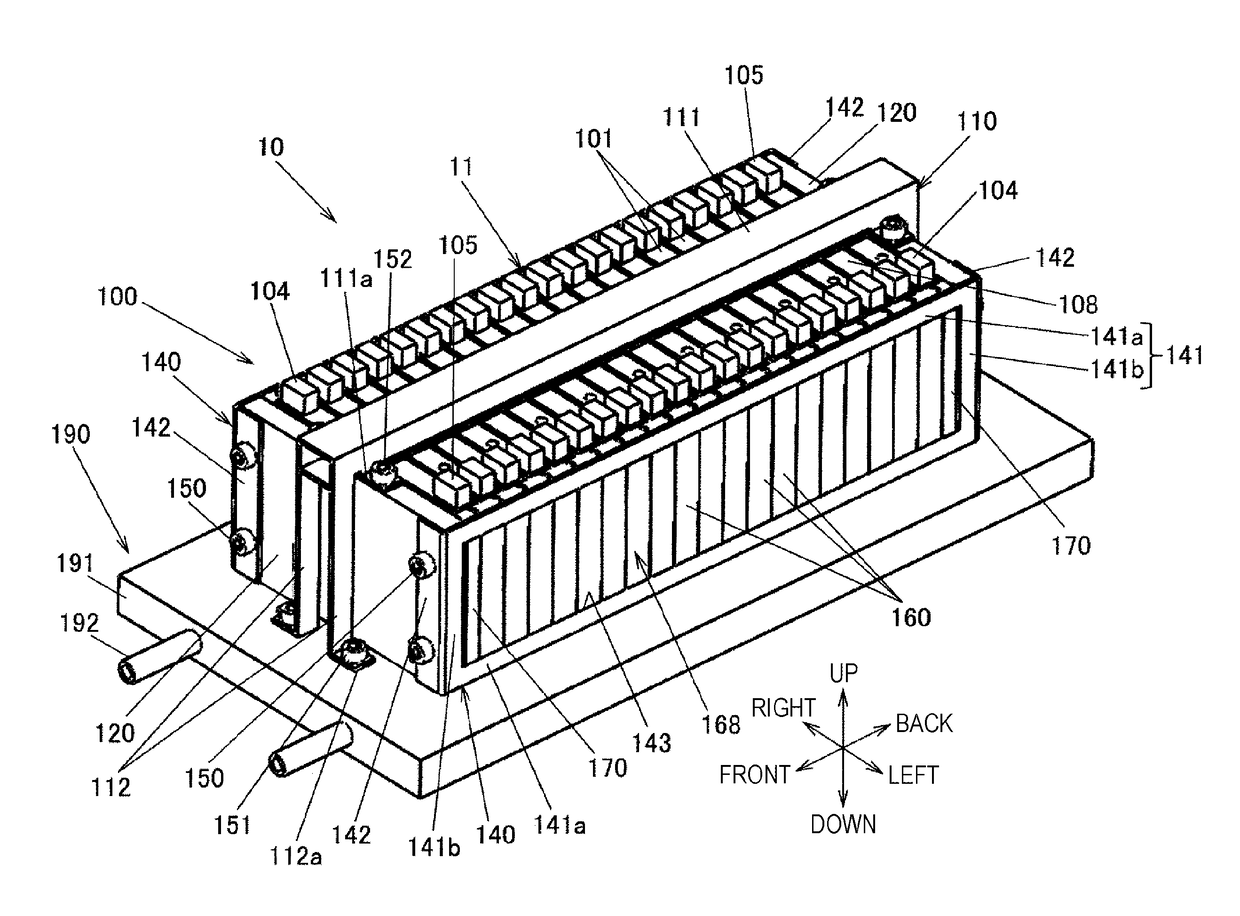
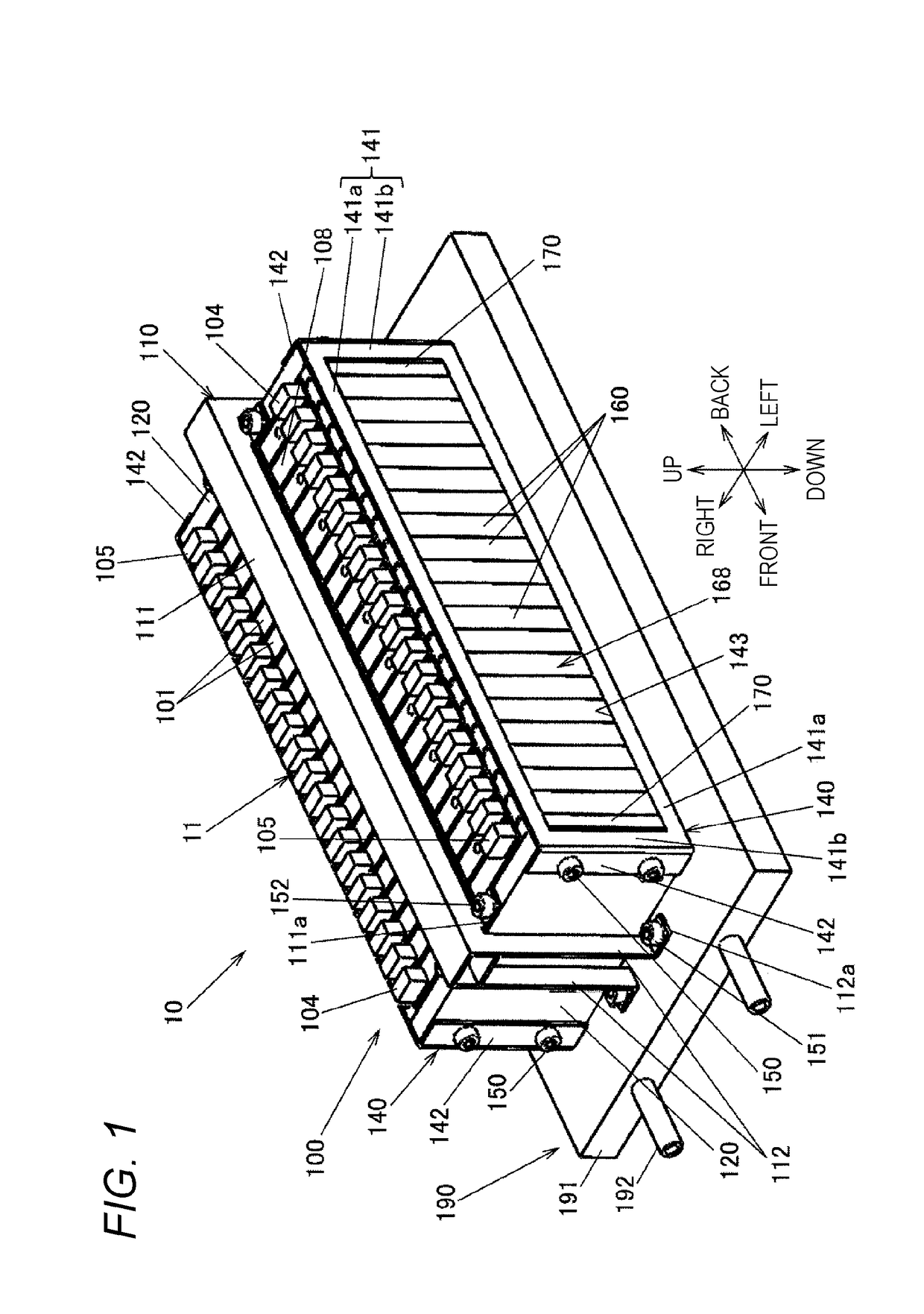
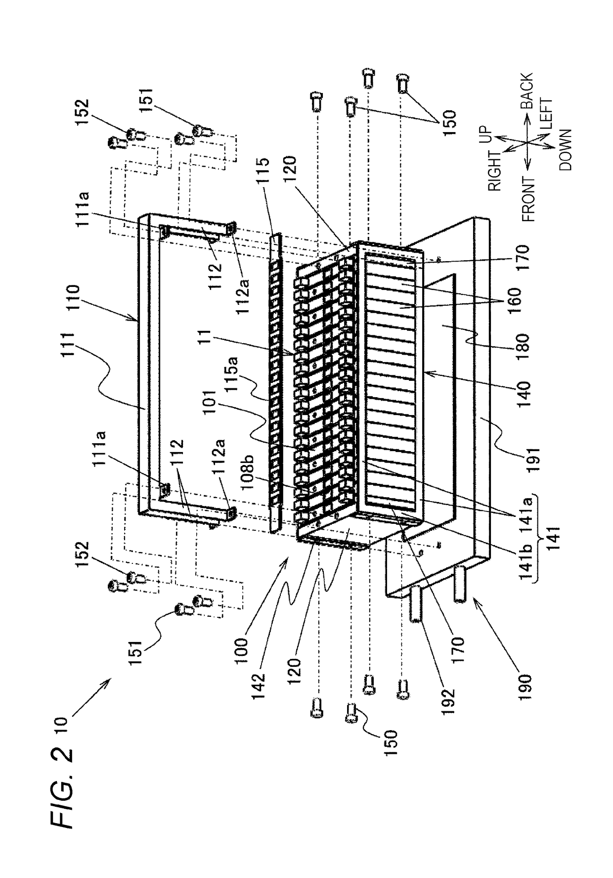
[0036]FIG. 1 is a perspective outer view of an electricity storage module 10 according to a first embodiment of the present invention. FIG. 2 is an exploded perspective view illustrating a configuration of the electricity storage module 10. The electricity storage module 10 is composed of a cooling structure 190 and an electricity storage block 100. The electricity storage block 100 includes an element stacked body 11 in which a plurality of cell batteries 101 is stacked and arranged, an integration mechanism that integrates the element stacked body 11, and a duct unit 110 as a press device that presses the element stacked body 11 toward the cooling structure 190.

[0037]FIG. 3 is an exploded perspective view illustrating a configuration of the element stacked body 11, showing part of the element stacked body 11. As illustrated in FIG. 3, the element stacked body 11 includes the plurality of cell batteries 101 and a plurality of battery holders 160 and 170. Each of the cell batteries ...

second embodiment

[0096]A second embodiment of the present invention will be described with reference to FIGS. 9 to 13. In these drawings, the components identical or equivalent to those in the first embodiment are given the same reference signs as those in the first embodiment and descriptions thereof are omitted. The differences from the first embodiment will be described below in detail.

[0097]FIG. 9 is similar to FIG. 3, which is an exploded perspective view illustrating a configuration of an element stacked body 21 of an electricity storage module according to the second embodiment of the present invention. FIG. 10 is a perspective view of an intermediate holder 260 constituting the element stacked body 21 illustrated in FIG. 9. FIG. 10 illustrates the intermediate holder 260 positioned at the right end of the element stacked body 21 and a part of the cell battery 101 in abutment with the intermediate holder 260 by chain double-dashed lines. FIG. 11 is a perspective view of the end holder 170.

[00...

third embodiment

[0113]A third embodiment of the present invention will be described with reference to FIGS. 14 to 19. In these drawings, the components identical or equivalent to those in the first embodiment are given the same reference signs as those in the first embodiment and descriptions thereof are omitted. The differences from the first embodiment will be described below in detail. FIG. 14 is an exploded perspective view illustrating a configuration of an electricity storage module 30 according to the third embodiment of the present invention. FIG. 15 is a bottom view of an electricity storage block 300 and the thermally-conductive sheet 180.

[0114]In the first embodiment, the outer surfaces of the bottom plates 109b of the cell batteries 101 serve as heat transfer surfaces attached closely to the thermally-conductive sheet 180, and the positive terminals 104 and the negative terminals 105 are provided on the cell covers 102 opposed to the bottom plates 109b (see FIG. 1).

[0115]In contrast, in...


PUM

PropertyMeasurementUnit
thermal conductivityaaaaaaaaaa
dimensionsaaaaaaaaaa
contrastaaaaaaaaaa

Abstract

An electricity storage block includes: an element stacked body in which a plurality of square electricity storage elements is stacked and arranged such that wide surfaces of the adjacent square electricity storage elements are opposed to each other; and a pressing device that presses the element stacked body toward the thermally-conductive sheet arranged on the heat transfer plate. The element stacked body includes holders having wide surface abutment parts in abutment with one of the wide surfaces in a pair in at least the predetermined square electricity storage element. The outer surfaces of the bottom plates of the square electricity storage elements are set as heat transfer surfaces thermally connected to the heat transfer plate via the thermally-conductive sheet. The heat-transfer surfaces protrude toward the heat transfer plate more than the end surfaces of the wide surface abutment parts at the heat transfer plate side.

Description

CROSS REFERENCE TO RELATED APPLICATION[0001]This application is a continuation of U.S. patent application Ser. No. 14 / 895,665 filed Dec. 3, 2015, which is a 371 national stage application of PCT / JP2014 / 064048, filed May 28, 2014, which is incorporated by reference as if fully set forth.TECHNICAL FIELD[0002]The present invention relates to an electricity storage block with a plurality of electricity storage elements electrically connected together and an electricity storage module in which the electricity storage block is thermally connected to a heat transfer plate via a thermally-conductive sheet.BACKGROUND ART[0003]Electricity storage modules installed in hybrid electric automobiles and purely electric automobiles include a large number of electricity storage elements such as lithium-ion batteries and nickel-hydrogen batteries. The electricity storage elements generate heat due to internal resistance at the time of charging and discharging, and suffer more likely lifetime-related ...

Claims


Application Information

Patent Timeline
Patent Type & Authority Applications(United States)
IPC IPC(8): H01M10/6556H01M10/04H01M10/613H01M10/647H01M50/209
CPCH01M10/0486H01M10/0481H01M10/6556H01M10/613H01M2220/20H01M10/647H01M10/625H01M2/1077H01M10/6555H01M10/655H01M10/12H01M50/209Y02E60/10Y02P70/50H01M50/249H01M50/251H01M10/627
Inventor KUBOTA, OSAMUSATO, AKIRAOJIMA, KAZUNORIAOKI, SADAYUKI
Owner HITACHI VEHICLE ENERGY
Why Eureka
Try Eureka