Engine control apparatus

a technology of control apparatus and engine, which is applied in the direction of electric control, engine starters, machines/engines, etc., can solve the problems of vibration, swing-back, and inability to know whether the piston is actually stopped at an appropriate position, so as to improve the effect of suppressing vibration and suppressing the occurrence of inverse rotation of the engin

Inactive Publication Date: 2019-08-08
DENSO CORP
View PDF4 Cites 3 Cited by
  • Summary
  • Abstract
  • Description
  • Claims
  • Application Information

AI Technical Summary

Benefits of technology

[0007]The present disclosure is mainly directed to providing an engine control apparatus which is capable of suppressing vibration in association with inverse rotation of an engine by suppressing occurrence of the inverse rotation of the engine.
[0010]According to the above-described configuration, it is determined whether or not the piston is located at a position, at which compression reactive force is received, at a time point at which rotation of the engine is stopped, and, in the case where it is determined that the piston is located at the position at which compression reactive force is received, positive torque is applied. In this case, by applying positive torque against the generated compression reactive force, it is possible to prevent the piston from being pushed back. By this means, it is possible to suppress occurrence of inverse rotation of the engine and suppress vibration in association with the inverse rotation of the engine.
[0014]The compression reactive force generated within the cylinder gradually decreases and finally disappears because air within the cylinder comes out as time passes. With the above-described configuration, after application of positive torque is started, application of the positive torque is stopped in association with disappearance of the compression reactive force. By this means, it is possible to prevent the engine from being rotated as a result of positive torque becoming excessive when compression reactive force disappears.
[0016]As time passes, the compression reactive force within the cylinder gradually decreases since rotation of the engine is stopped. With the above-described configuration, a configuration is employed in which the positive torque applied to the engine output shaft is gradually reduced as time passes in accordance with change of the pressure within the cylinder. By this means, it is possible to maintain an appropriate balance between the compression reactive force and force of the positive torque.
[0020]With the above-described configuration, first, the piston to which the counter torque is applied is controlled to be stopped at a position in the first half of the expansion stroke, as the crank angle stop processing. Then, in the case where the piston is not stopped at the desired position, positive torque is applied as backup processing. By this means, it is possible to further suppress occurrence of inverse rotation of the engine, so that it is possible to improve an effect of suppressing vibration.

Problems solved by technology

However, in the case where control is performed so that the piston gets over the top dead center, it is not certain whether the piston is actually stopped at an appropriate position.
As a result, there is a probability that swing-back may occur again.
In such a case, the engine inversely rotates by the piston being pushed back, and, as a result, vibration occurs.

Method used


Image

  • Engine control apparatus
  • Engine control apparatus
  • Engine control apparatus

Examples


Embodiment Construction

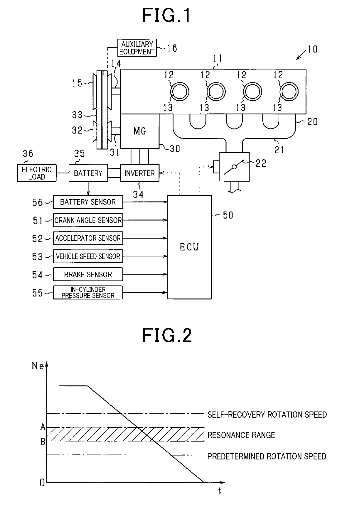
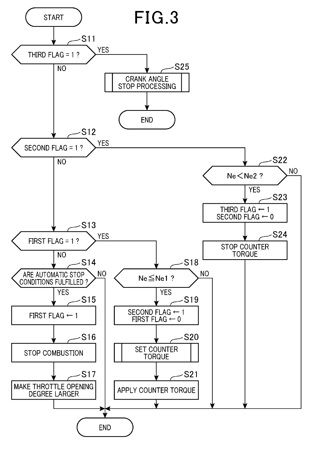
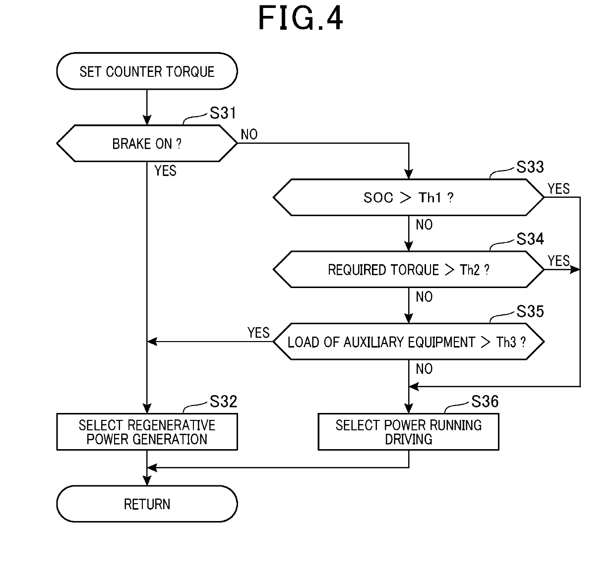
[0031]An embodiment of the present disclosure will be described below on the basis of the drawings. In the present embodiment, a control system for an engine installed in a vehicle is embodied. In the control system, an operation state, or the like, of the engine is controlled mainly with an electronic control unit (hereinafter, referred to as an ECU). An overall schematic diagram of the present system is illustrated in FIG. 1.

[0032]In a vehicle 10 illustrated in FIG. 1, an engine 11 is a four-stroke engine which is driven through combustion of fuel such as gasoline, and which repeatedly performs respective strokes of intake, compression, expansion and exhaust. The engine 11 has four cylinders 12, and a piston 13 is disposed in each of the cylinders 12. Further, the engine 11 includes a fuel injection valves (not illustrated), ignition devices (not illustrated), or the like, as appropriate. Note that, while, in the present embodiment, an engine with four cylinders is illustrated, th...


PUM


Abstract

An ECU is applied to an engine system including an engine and an MG. The ECU determines whether or not a piston is located at a position, at which compression reactive force is received, at a time point at which engine speed reaches zero after combustion of the engine is stopped. Further, in a case where the ECU determines that the piston is located at the position at which compression reactive force is received, the ECU stops the piston by applying positive torque on a positive rotation side to a crank shaft by the MG.

Description

CROSS-REFERENCE TO RELATED APPLICATION[0001]The present application is based on and claims the benefit of priority from earlier Japanese Patent Application No. 2016-094758 filed on May 10, 2016, the description of which is incorporated herein by reference.TECHNICAL FIELD[0002]The present disclosure relates to an engine control apparatus.BACKGROUND ART[0003]In a vehicle, when an engine is stopped, there is a case where vibration may occur by swing-back (inverse rotation) of rotation of the engine, and the vibration may provide a feeling of discomfort to the driver. This occurs by a piston being pushed back by a pressure within a cylinder when rotation of an engine output shaft is stopped.[0004]For example, in a technique disclosed in PTL 1, in a vehicle having an idling stop function, swing-back occurring when rotation of an engine output shaft is stopped is predicted. Then, in the case where it is determined that swing-back will occur, control is performed so that a piston gets over...

Claims


Application Information

Patent Timeline
Patent Type & Authority Applications(United States)
IPC IPC(8): F02N19/00F02N11/08
CPCF02N19/005F02N11/0814F02N2300/104F02N2250/04F02N2200/021F02N2019/008F02D43/00F02D45/00F02D29/02B60W10/08F02N11/04F02N2019/007B60W10/06F02D29/06F02D2250/24F02D41/042
Inventor HOSHINO, SHOGO
Owner DENSO CORP
Why Eureka
Try Eureka