Gear Drive Two-Wheel Scooter

a two-wheeled, scooter technology, applied in the field of two-wheeled scooters, can solve the problems of inconvenient swerving in narrow spaces, too large synchronous movement scooters, etc., and achieve the effect of increasing stability, increasing comfort and safety, and facilitating the learning curve for the beginner

Inactive Publication Date: 2018-05-10
ZAKE IP HLDG LLC
View PDF0 Cites 16 Cited by
  • Summary
  • Abstract
  • Description
  • Claims
  • Application Information

AI Technical Summary

Benefits of technology

[0003]The present disclosure describes a scooter, personal recreational toy, or fun travel device that is for a single user to ride, and by shifting their weight or changing the angle of their feet, can cause the device to steer, accelerate, decelerate, and perform various tricks. The device improves on the Chen patent by including a center section that couples the two halves. The left and right sections are tied together through a spider gear held in the center, allowing controlled movement between the left and right sections. By controlling the movement between the left and right sections, stability is increased, allowing for increased comfort and safety, particularly for the novice. Optionally, a return-to-center feature can be implemented using a spring, magnet, or other means to further stabilize the scooter and provide an easier learning curve for the beginner.
[0004]The present disclosure also relates to a synchronous movement scooter which includes a left side, a right side, and a rotating mechanism located between and coupled to both left and right sides. The rotating mechanism is meshed with a gear portion of the left side and a gear portion of the right side respectively through a drive gear. When a user angles the left side or the right side to turn over, the right side or the left side is automatically driven by the drive gear to turn over reversely, thus the synchronous movement scooter is controlled to turn left or right; moreover, the radius of rotation of the synchronous movement scooter is smaller so that it is easy for the user to operate and control the synchronous movement scooter, and hazards occurred during operating and controlling is prevented.
[0013]Compared with the prior art, the present disclosure may acquire the following technical effects. The left and right scooter sides are automatically driven by the rotating mechanism to turn over relatively, so that the synchronous movement scooter is driven to rotate in a small radius of rotation; the insides of the left and right scooter bodies are provided with the sensing device respectively, and each of the sensing device senses the change of the gravity center of the corresponding side, and controls the rolling directions and speeds of the left and right wheel bodies; the left and right scooter bodies are provided with the infrared sensor or the piezoelectric sensor and the trample indicator lamp respectively, so that the object of identifying whether a user steps on the device, synchronous movement scooter is achieved; the left and right scooter bodies are provided with the antiskid pedal respectively, which prevents the user from slipping and falling over the scooter; and the left and right scooter bodies may optionally contain anti-collision sensors respectively to sense the distance between the synchronous movement scooter and an obstacle; when the distance is less than a safe distance, the synchronous movement scooter may slow down or stop moving, which prevents the scooter from colliding with the obstacle.

Problems solved by technology

Generally, the synchronous movement scooter may be operated and controlled to swerve by angling the left and right sides or changing center of gravity; however, the radius of rotation of the synchronous movement scooter is too large, which is inconvenient to swerve in narrow space.

Method used


Image

  • Gear Drive Two-Wheel Scooter
  • Gear Drive Two-Wheel Scooter
  • Gear Drive Two-Wheel Scooter

Examples


Embodiment Construction

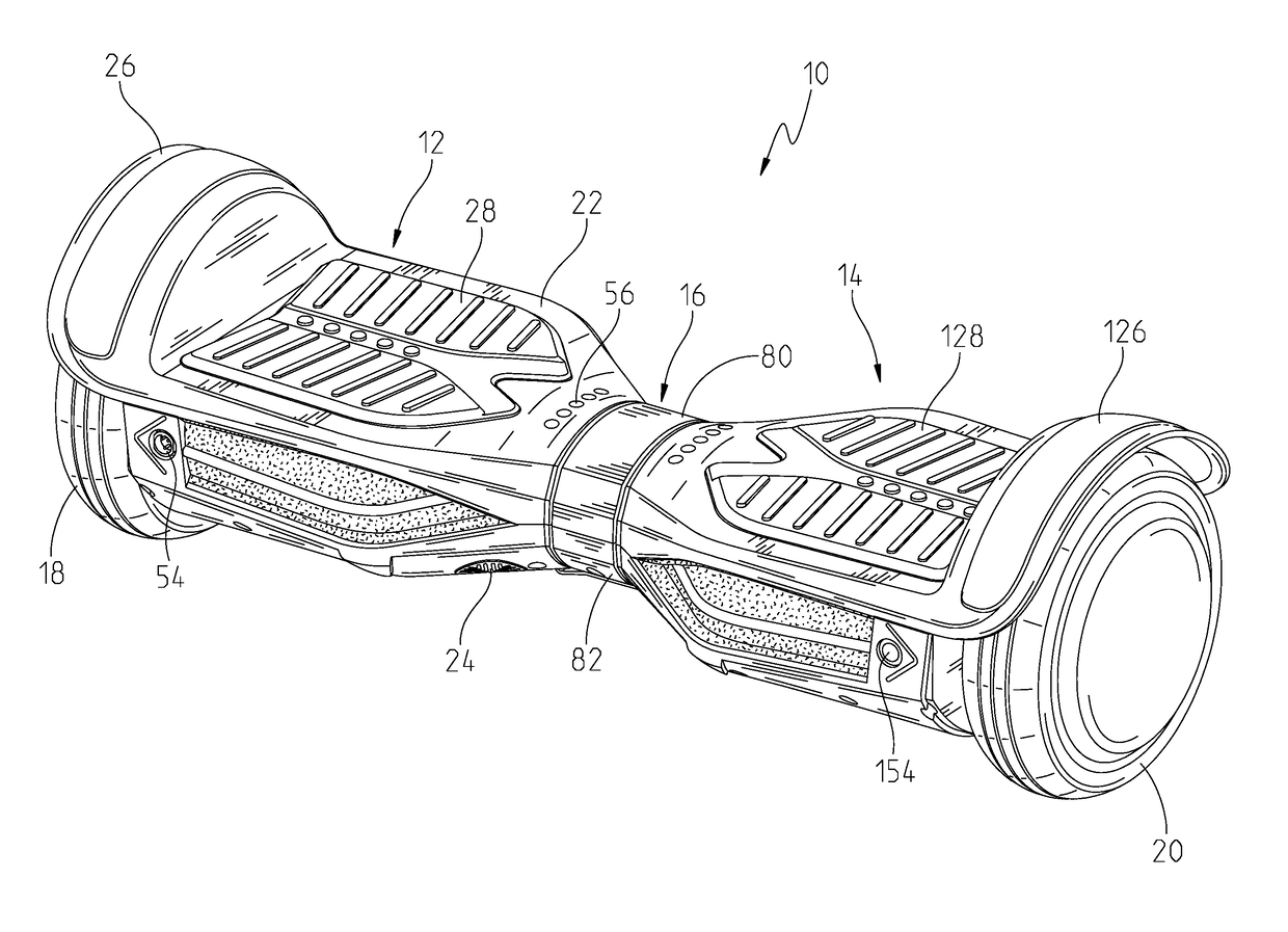
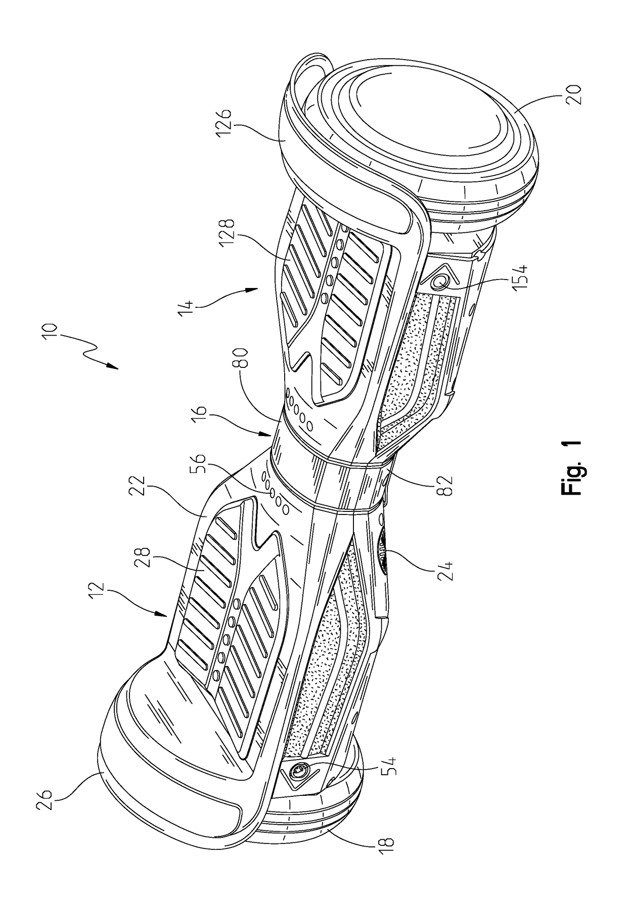
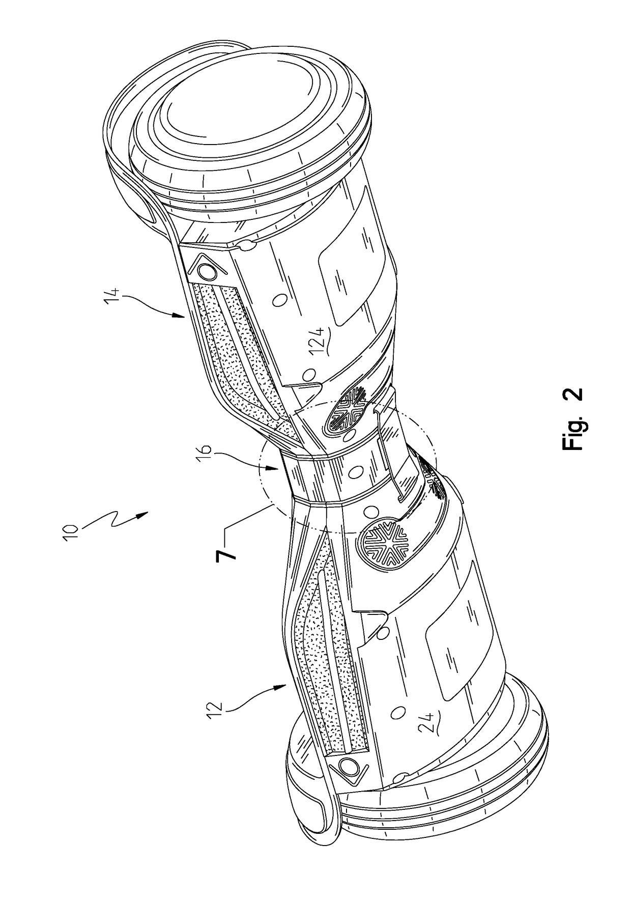
[0029]A scooter 10 is shown in FIGS. 1-5 and has three primary portions. The portions include a left side 12, a right side, 14, and a center section 16. The left side 12 has a left wheel 18 and the right side 14 has a right wheel 20. Both are adapted to roll on the ground or other horizontal surface.

[0030]Turning now to the detail of the left side 12, an upper housing 22 and a lower housing 24 form a protective and decorative cover for internal components and electrical connections, shown in FIGS. 6, 8, 10. As shown in FIG. 8, the left wheel 18 is attached on one side and is covered by a fender portion 26 of the upper housing 22. The left side 12, specifically the upper housing 22, further includes an anti-slip foot pad 28 that is made for the user to place their weight or stand on. The foot pad 28 may also contain a presence sensor 30 to detect the rider's presence. Directly underneath the foot pad 28 is a structure 31 that has downwardly extending protrusions 29 that change the st...


PUM


Abstract

A gear drive balancing scooter is provided that has a left side, a right side, and a center section located between the left and right side. The center section is coupled to the right and left sides through a gear. As the left side moves with respect to the center section, the right side moves in an opposite direction with respect to the center section. Both sides have a respective wheel motor assembly that is used to balance the scooter. To steer the scooter, the user angles one side differently than the other side. The angle of each side determines the rate and direction that each wheel motor assembly rotates. An optional staff extends upwardly from the center section to provide stability.

Description

BACKGROUND OF THE INVENTION[0001]This present disclosure relates to riding toys, namely two-wheeled scooters, designed for a single person to stand on and control by moving the position and angle of their feet. Other devices exist in the art, such as the well-known Segway® transporter, various aspects being covered in many U.S. patents. These require a steering bar or other member that the user rotates or twists to accomplish the steering. The forward and reverse direction is caused by the user shifting their weight. Another example is by Shane Chen, U.S. Pat. No. 8,738,278, covering a personal transporter with independently moveable foot placement sections. The Chen patent removes the steering bar and relies on the user tilting the independently moveable foot placement sections to move forward, backward, and steer.[0002]The prior art has still-unresolved issues, such as the inherent instability of independently moveable foot placement sections. By allowing them to be fully independ...

Claims


Application Information

Patent Timeline
Patent Type & Authority Applications(United States)
IPC IPC(8): B62K11/00B62K3/00B62K11/14B62M7/12B62J99/00
CPCB62K11/007B62K3/002B62K11/14B62J2099/002B62J99/00B62J2099/0013B62M7/12B60L3/08B60L15/2036B60L2200/16B60L2200/20B60L2200/24B60L2220/42B60L2250/10B60L2250/22B60L50/52B62J43/30B62J45/20B62J45/415B62J50/21Y02T10/64Y02T10/70Y02T10/72
Inventor LANKFORD, GARRICK THEODOREMARSTON, MICHAEL DAVIDWANG, WEIWEIWANG, YONG
Owner ZAKE IP HLDG LLC
Why Eureka
Try Eureka