Slider for slide fastener

a technology of sliding and fasteners, applied in the field of sliding, can solve the problems of high production cost, inconvenient installation, complex structure, etc., and achieve the effects of reducing the pivoting friction of the connecting shaft, improving the stability of the pull-tab, and facilitating the assembly and disassembly of the pull-tab

Active Publication Date: 2018-05-17
IDEAL FASTENER GUANG DONG IND LTD
View PDF10 Cites 8 Cited by
  • Summary
  • Abstract
  • Description
  • Claims
  • Application Information

AI Technical Summary

Benefits of technology

[0038]Said pull-tab through hole could improve the stability of the pull-tab when it is assembled.
[0039]Preferably, both ends of the connecting shaft is set as truncated cone shape, which could facilitate the assembly and disassembly of the pull-tab and reduce the pivoting friction of the connecting shaft when the slider is in use, thus prolonging the service life of the pull-tab and the slider.
[0040]Preferably, the length of the connecting shaft is set as 1.8˜2.3 times of the anterior-end width of the pull-tab body, the ratio of the length of the connecting shaft to the anterior-end width of the pull-tab body is set as the same with the befitting length of the connecting shaft to the pull-tab and slider base, which could guarantee the pull-tab set on a preferable position on the slider base and facilitate the assembly of the slider.
[0041]Preferably, the depth of the spring mounting hole is set as ½˜⅔ of the length of the spring, the ratio of the depth of the spring mounting hole to the length of the spring works in combination with the spring mounting hole, the spring assembling hole on the second upper blade lateral side and the spring structure, thus making the first extending end of the spring clip into the annular slot on the second upper blade lateral side when the slider is assembled, and ensuring the stability of the spring when the slider is assembled.
[0042]The invention has the advantages that the slider disclosed by the present invention comprises a slider base, a pull-tab, a connecting shaft and a spring; said pull-tab is integrated with the connecting shaft; a spring mounting part and a locking part is set at the anterior-end of the pull-tab body, wherein the spring mounting part and the locking part are adjacent to each other; the spring mounting part has a spring mounting hole and a spring mounting slot interconnected with the spring mounting hole; the upper blade has a square-shaped notch for disposing the pull-tab, a first upper blade lateral side and a second upper blade lateral side set at both sides of the square-shaped notch; a first connecting-shaft through hole and a second connecting-shaft through hole is set at the first upper blade lateral side and the second upper blade lateral side respectively; the second connecting-shaft through hole matches with the spring mounting hole and spring mounting slot set on the spring mounting part. The structure of the slider disclosed by the present invention is a new technical design with simplified structure and is facilitated for industrialized production with low cost. The pull-tab is integrated with the connecting shaft, which facilitates the slider mounting on the upper slider on the slider base. When the pull-tab is assembled, the spring gets into the spring mounting part at the anterior-end of the pull-tab and is assembled through the second connecting-shaft through hole, thus simplifying assembly technique and steps of the slider, which facilitates the assembly of the slider and improves the production efficiency of slider, and achieves steady structure and long service life of the slider after it is assembled.

Problems solved by technology

The above mentioned slider have a very complex structure, inconvenient installation, high production cost and isn't beneficial to mass production.

Method used


Image

  • Slider for slide fastener
  • Slider for slide fastener
  • Slider for slide fastener

Examples


embodiment 1

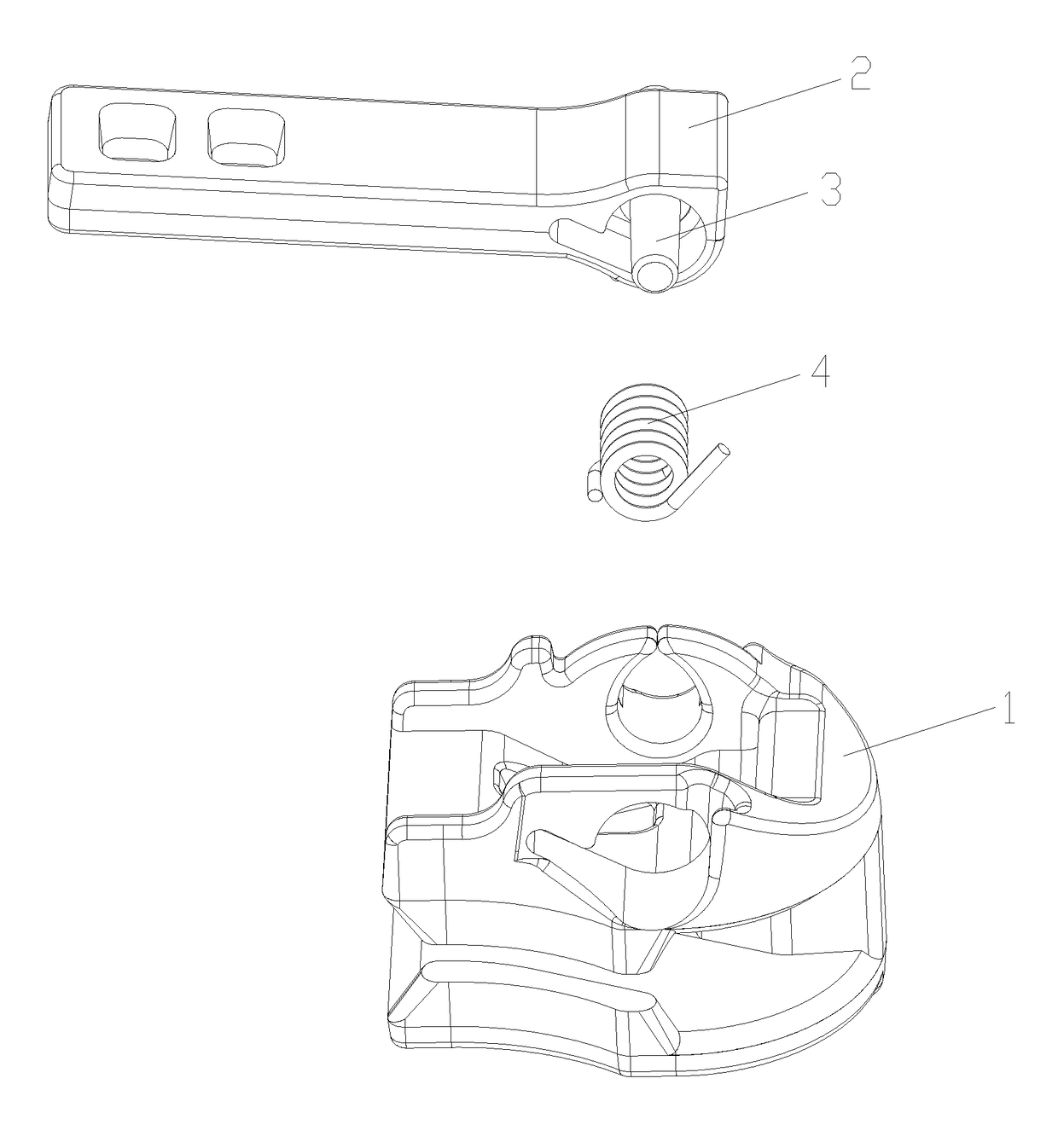
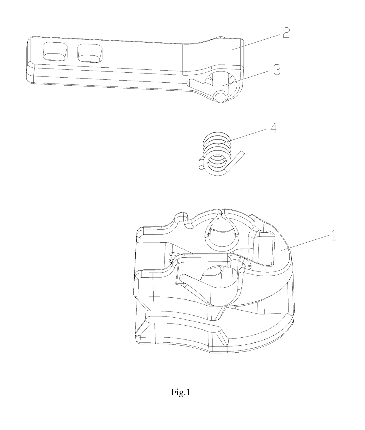
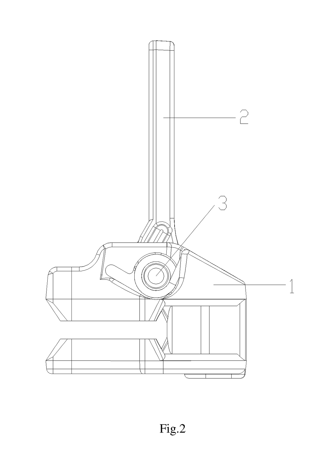
[0064]Refer to FIG. 1 to FIG. 13, the slider disclosed by the present invention, comprising: a slider base 1, a pull-tab 2, a connecting shaft 3 and a spring 4; the slider base 1 comprises an upper blade 11, a lower blade 13, and a connecting pin 12 connecting the upper blade 11 and the lower blade 13;

[0065]said pull-tab 2 is integrated with the connecting shaft 3; the pull-tab 2 comprises a pull-tab body 21, with a spring mounting part 22 and a locking part 23 set at the anterior-end of the pull-tab body 21, wherein the spring mounting part 22 and the locking part 23 are adjacent to each other; the anterior-end-face of the pull-tab body 21 is set as a locking vertical plane 24 and the bottom of the pull-tab body 21 is set as cambered surface; the connecting shaft 3 is fixed to the anterior-end of the pull-tab body 21 and the length of the connecting shaft 3 is larger than the width of the anterior-end of the pull-tab body 21; the connecting shaft 3 runs through the spring mounting ...

embodiment 2

[0083]Refer to FIG. 14 to FIG. 19, the Embodiment 2 differs from Embodiment 1 that a spring mounting part 22 and a locking part 23 is set at the anterior-end of the pull-tab body 21, wherein the spring mounting part 22 and the locking part 23 are adjacent to each other; the anterior-end-face of the locking part 23 is set as a locking vertical plane 24 and the bottom of the locking part 23 is set as cambered surface; an interconnected gap is set between the anterior-end-face of the spring mounting part 22 and the bottom of the spring mounting part 22; the connecting shaft 3 is fixed to the anterior-end of the pull-tab body 21 and the length of the connecting shaft 3 is larger than the width of the anterior-end of the pull-tab body 21; the connecting shaft 3 runs through the spring mounting part 22 and the locking part 23 and is set closer to the anterior-end-face of the locking part 23, and extends to both sides of the anterior-end of the pull-tab body 21; the spring mounting part 22...


PUM


Abstract

A slider, includes a slider base, a pull-tab, a connecting shaft and a spring; the slider base includes an upper blade, a lower blade, and a connecting pin connecting the upper blade and the lower blade; said pull-tab is integrated with the connecting shaft; the pull-tab includes a pull-tab body, with a spring mounting part and a locking part set at the anterior-end-face of the pull-tab body; the anterior-end-face of the pull-tab body is set as a locking vertical plane and the bottom of the pull-tab body is set as cambered surface; the connecting shaft is fixed to the anterior-end of the pull-tab body and the length of the connecting shaft is larger than the width of the anterior-end-face of the pull-tab body; the connecting shaft runs through the spring mounting part and the locking part and extends to both sides of the anterior-end of the pull-tab body.

Description

CROSS-REFERENCE TO RELATED APPLICATION[0001]The present application is a continuation application of PCT application No. PCT / CN2016 / 105789 filed on Nov. 14, 2016, the contents of which are hereby incorporated by reference.FIELD OF THE INVENTION[0002]The present invention relates to the field of zipper, and more particularly to a slider.BACKGROUND OF THE INVENTION[0003]Zipper is fastenings to combine or separate items with continuous teeth, now it is widely used in clothes, bags, tents and so on. Zipper comprises teeth, slider, top stopper, bottom stopper, and locking pieces and so on, wherein slider is moving parts that make the teeth engage with or separate from each other. Generally there are two tapes for the zipper with a sequence of teeth respectively, said sequence of teeth are alternatively staggered arranged; the slider clamps the teeth at both sides and slide with the aid of a pull-tab, thus making the teeth engage with or separate from each other.[0004]Slider is the one of...

Claims


Application Information

Patent Timeline
Patent Type & Authority Applications(United States)
IPC IPC(8): A44B19/26A44B19/30
CPCA44B19/262A44B19/306A44B19/26A44B19/305Y10T24/2568
Inventor HUNG, FRANKLIN CHI YENQIU, GUOLIANGQIU, WEILYU, ZONGJIANWU, FUKANG
Owner IDEAL FASTENER GUANG DONG IND LTD
Why Eureka
Try Eureka