Cleaning device

a vacuum cleaner and cleaning device technology, applied in the field of vacuum cleaners, can solve the problems of affecting the cleaning effect of vacuum cleaners, so as to achieve the effect of less parts and materials and convenient cleaning and maintenan

Active Publication Date: 2018-05-17
BLACK & DECKER INC
View PDF0 Cites 11 Cited by
  • Summary
  • Abstract
  • Description
  • Claims
  • Application Information

AI Technical Summary

Benefits of technology

[0016]Preferably wherein the vacuum cleaner comprises a releasable latch mechanism for selectively releasing the dirt container from the housing. Preferably the latch mechanism comprises a first portion of the latch mechanism on the housing and a second reciprocal portion of the latch mechanism on the dirt container. Preferably the latch mechanism comprises a latch release button mounted in the housing for actuating the latch mechanism. Preferably the latch release button is mounted in the first handle and actuatable with a user's thumb. This means that the user is less likely to accidently detach the dirt container from the housing.
[0017]Preferably the filter is removable from the dirt container. Preferably the filter is mountable on the dirt container and extends across a side of the dirt container opposite to the dirty air inlet. Preferably filter is a wall of the dirt container. Since the filter is removable it is replaceable and can be easily cleaned and maintained. The filter forms a wall of the dirt container and this makes a more compact vacuum cleaner requiring less parts and materials.

Problems solved by technology

Some vacuum cleaners have complicated mechanisms for emptying the dirt container.
The user may not understand how to release the lid of the dust container and may damage the latch mechanism by attempting to prise the lid open.
In order to empty the storage chamber, the user must touch the dirty filter and thereby getting their hands soiled when emptying the dust container.
This is undesirable because the vacuum cleaner itself can end up distributing the dirt and debris further afield.

Method used


Image

  • Cleaning device
  • Cleaning device
  • Cleaning device

Examples


Embodiment Construction

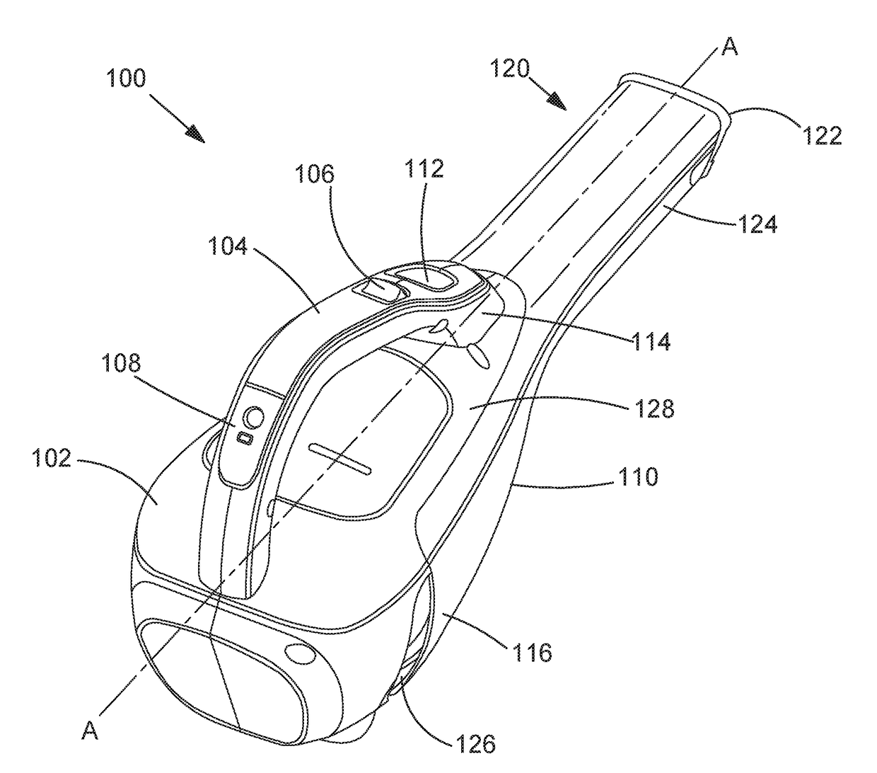
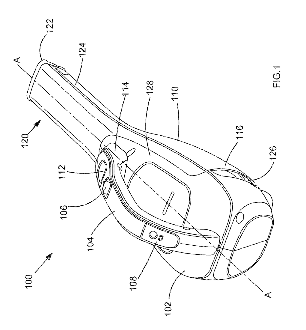
[0026]FIG. 1 shows a perspective view of vacuum cleaner 100. The vacuum cleaner 100 as shown in FIG. 1 is a handheld vacuum cleaner, but the in other embodiments the vacuum cleaner 100 may be an upright vacuum cleaner, a stickvac, a canister vacuum cleaner or any other type of vacuum cleaner. References to vacuum cleaner 100 hereinafter will be in reference to the handheld vacuum cleaner as shown in the Figures.

[0027]Vacuum cleaner 100 has a housing 102 which comprises two clam-shell halves fixed together. A motor-fan assembly (reference 500 in FIG. 5) is housed within the housing 102. The motor fan assembly 500 is arranged to create a negative pressure for creating an airflow for sucking up dirt and debris.

[0028]The housing 102 comprises a first handle 104. The first handle 104 is integral with the housing 102 and the user grips the first handle when operating the vacuum cleaner 100. The handle comprises an ON / OFF switch 106 for operating the vacuum cleaner. In some embodiments the...


PUM


Abstract

A vacuum cleaner comprises a housing and a motor fan assembly arranged to generate an air flow. A detachable dirt container is mountable to the housing; the dirt container having a dirty air inlet in fluid communication with the motor fan assembly. A filter is for separating dirt from the air flow, the filter being mounted between the dirt container and the motor fan assembly. The housing comprises at least one air outlet for exhausting clean air from the motor fan assembly. Wherein the detachable dirt container comprises at least one projecting lip arranged to overlap the at least one air outlet when the detachable dirt container is mounted on the housing and direct the air flow away from the dirty air inlet.

Description

CROSS-REFERENCE TO RELATED APPLICATION[0001]This application claims priority to European Patent Application No. 16199161.7 filed Nov. 16, 2016. The entire contents of that application are expressly incorporated herein by reference.FIELD OF THE INVENTION[0002]The present invention relates to a vacuum cleaner.BACKGROUND OF THE INVENTION[0003]Many people use vacuum cleaners to clean and tidy their homes. Normally vacuum cleaners are used to pick up dust and debris using a negative pressure. Dust and debris is entrained in an air flow and sucked into the body of the vacuum cleaner wherein the dust and debris are separated from the air flow. Once separated from the air flow, the dust and debris are collected and usually emptied in a dustbin at the user's convenience.[0004]Some vacuum cleaners have complicated mechanisms for emptying the dirt container. For example EP 1 377 197 discloses a trigger mechanically coupled to a rod and latch release mechanism for a lid of the dust container. T...

Claims


Application Information

Patent Timeline
Patent Type & Authority Applications(United States)
IPC IPC(8): A47L9/14A47L5/24A47L9/28A47L9/32A47L9/12
CPCA47L9/149A47L5/24A47L9/2857A47L9/322A47L9/12A47L9/00A47L9/10A47L7/0019A47L9/0081
Inventor WALKER, ANDREW
Owner BLACK & DECKER INC
Why Eureka
Try Eureka