Lever lock-type male connector and male connector assembly

a lever lock and connector technology, applied in the field of lever lock-type male connectors and male connector assemblies, can solve the problems of difficult release of screwed connections, thread breaking, and difficulty for users to accurately know the screwed state of male threads and female threads, and achieve excellent ease of operation for connection and disconnection.

Active Publication Date: 2018-05-17
JMS CO LTD
View PDF8 Cites 8 Cited by
  • Summary
  • Abstract
  • Description
  • Claims
  • Application Information

AI Technical Summary

Benefits of technology

[0014]The connector main body includes the lever that is held by the base in a seesaw manner. The lever includes the locking claw that is engageable with the female connector. When the lock ring is at the first position, the lever is elastically pivotable such that the locking claw moves away from the male luer. Therefore, as is the case with a male connector including a conventional lever-type lock mechanism, the male connector and the male connector assembly of the present invention, which have the connector main body, provide excellent ease of operations for connection and disconnection to and from the female connector.
[0015]When the lock ring is at the second position, the lock ring restricts the lever from pivoting such that the locking claw moves away from the male luer. Thus, the likelihood of a locked state being unintentionally cancelled due to an external force acting on the operating portion can be reduced by moving the lock ring to the second position.

Problems solved by technology

A screw lock mechanism has a problem in that it is difficult for a user to accurately know the screwed state of the male thread and the female thread.
Thus, if the male thread and the female thread are excessively strongly screwed together, problematic situations, such as the threads breaking and the screwed connection becoming difficult to release, may occur.
Conversely, if the male thread and the female thread are loosely screwed together, problematic situations, such as loosening of the screwed connection between the male thread and the female thread as well as the resulting leakage of a liquid through a gap between the male tapered surface and the female tapered surface, disconnection of the male connector and the female connector, and the like, may occur.

Method used


Image

  • Lever lock-type male connector and male connector assembly
  • Lever lock-type male connector and male connector assembly
  • Lever lock-type male connector and male connector assembly

Examples


embodiment 1

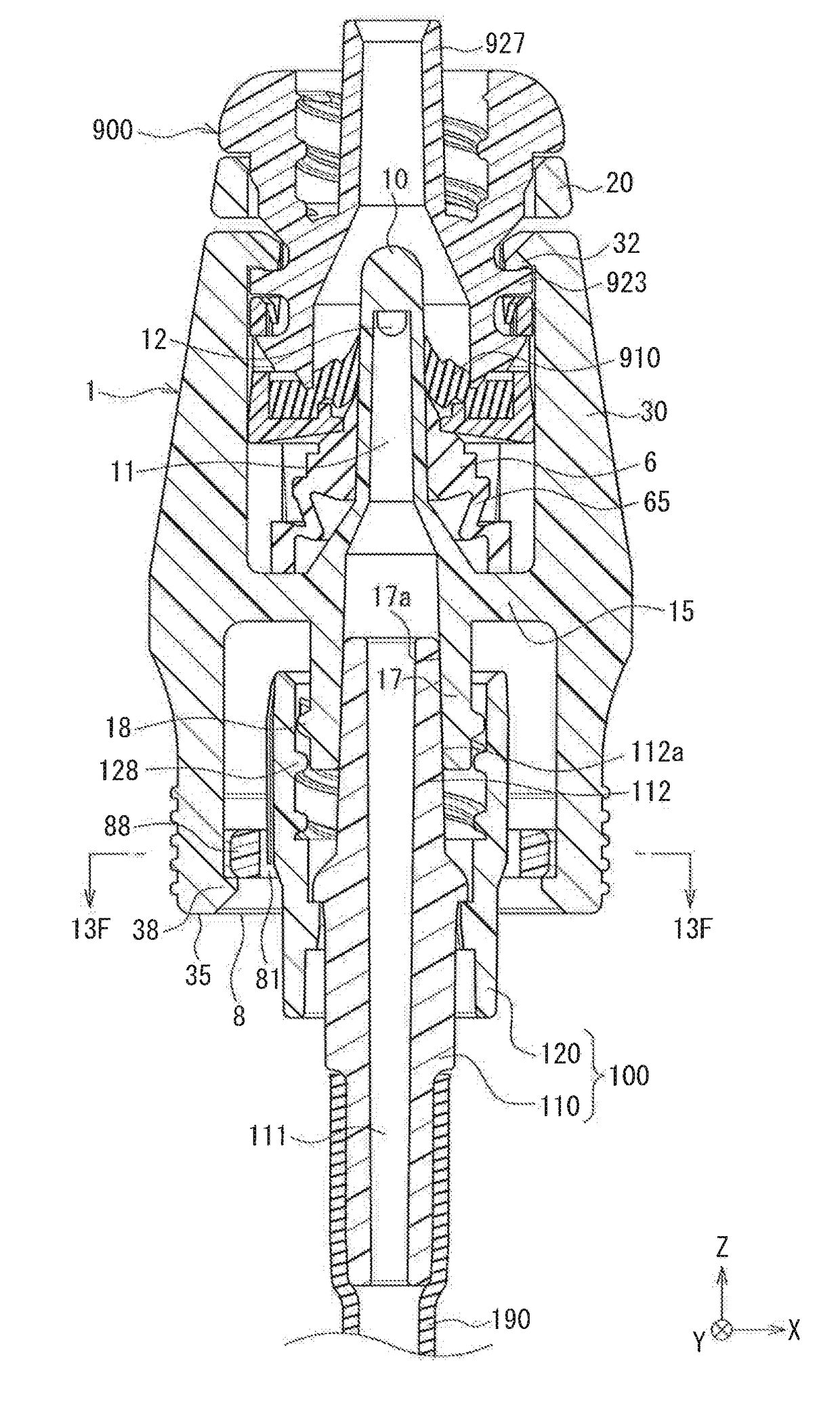
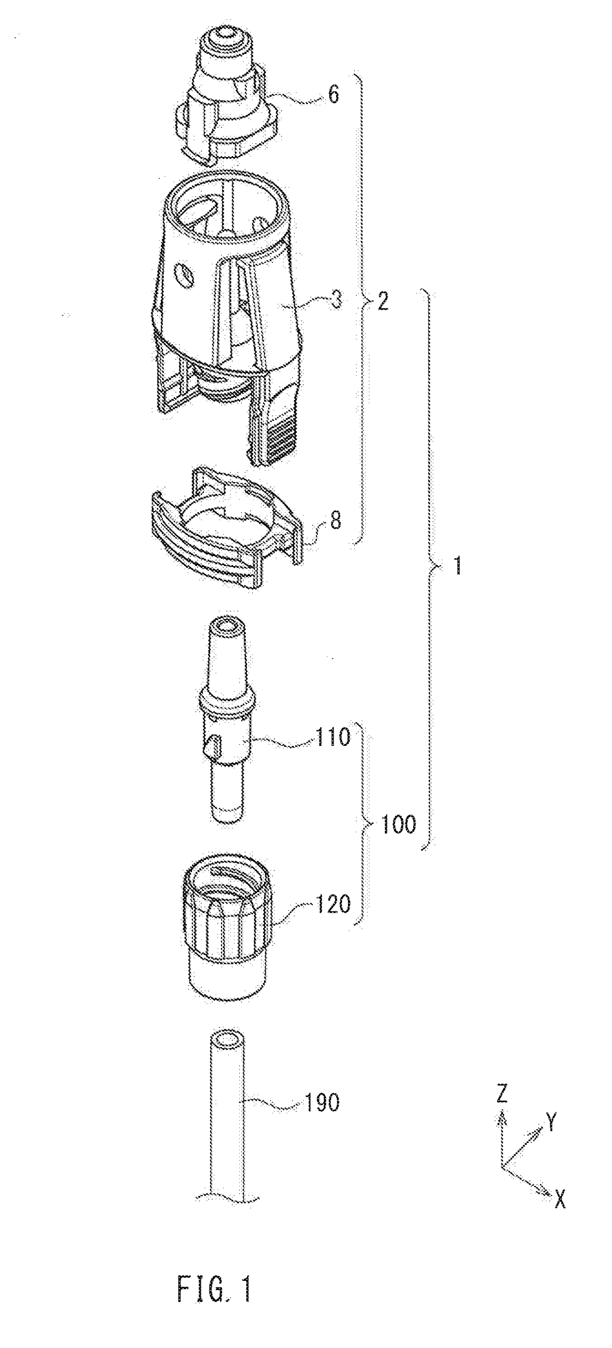
[0090]FIG. 1 is an exploded perspective view of a male connector assembly 1 according to Embodiment 1 of the present invention. The male connector assembly 1 includes a lever lock-type male connector (hereinafter simply referred to as “male connector”) 2 and a screw lock-type connector 100. The male connector 2 includes a connector main body 3, a shield 6, and a lock ring 8. The screw lock-type connector 100 includes a luer main body 110 and a lock nut 120. A flexible tube 190 is connected to the male connector 2 via the screw lock-type connector 100.

[0091]Hereinafter, the various portions will be sequentially described.

1. Male Connector

1. 1. Connector Main Body

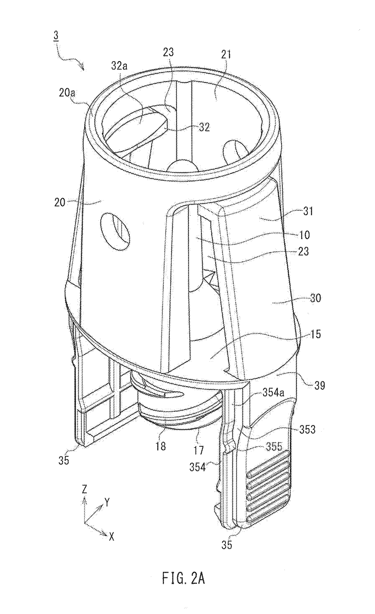
[0092]The connector main body 3 constituting the male connector 2 will be described. FIG. 2A is a perspective view of the connector main body 3 when viewed from above, and FIG. 2B is a perspective view of the connector main body 3 when viewed from below. FIGS. 2C, 2D, and 2E are a front view, a side view, and a plan view, in ...

embodiment 2

[0202]Embodiment 2 of the present invention differs from Embodiment 1 mainly in the configurations of the connector main body and the lock ring. Hereinafter, Embodiment 2 will be described focusing on the differences from Embodiment 1.

1. Connector Main Body

[0203]FIG. 14A is a perspective view of a connector main body 203 according to Embodiment 2 when viewed from above, FIG. 14B is a perspective view of the connector main body 203 when viewed from below, and FIG. 14C is a plan view of the connector main body 203. In FIGS. 14A to 14C, members corresponding to the members shown in FIGS. 2A to 2G are denoted by the same reference numerals as those in FIGS. 2A to 2G.

[0204]As can be easily understood by comparison of FIG. 14C with FIG. 2E, four cut-outs 215n are provided in the base 15 of the connector main body 203. The cut-outs 215n are provided in regions of the outer end edge of the base 15 other than the portions (portions on the major axis 15a and portions on the minor axis 15b) wh...


PUM


Abstract

Levers (30) are connected to a base end portion (13) of a male luer via a base (15). Each lever includes a locking portion (31) and an operating portion (35). A locking claw (32) protrudes from each locking portion toward the male luer. A lock ring (8) is provided opposing inner surfaces of the operating portions. The lock ring is movable between a first position at which the lock ring is located close to the base and a second position at which the lock ring is located away from the base. When the lock ring is at the first position, the levers are pivotable such that the locking claws move away from the male luer. When the lock ring is at the second position, the lock ring restricts the levers from pivoting such that the locking claws move away from the male luer.

Description

TECHNICAL FIELD[0001]The present invention relates to a male connector including a lever-type lock mechanism for maintaining a state in which the male connector is connected to a female connector. The present invention also relates to a male connector assembly including the male connector.BACKGROUND ART[0002]In the field of medicine, circuits (lines) are used to convey various liquids such as medicinal solutions, infusion solutions, and blood. Such circuits are generally formed by connecting containers, various instruments, tubes, and the like. In order to connect different members, a connecting device constituted by a male connector and a female connector is used.[0003]Many connecting devices for medical use are provided with a lock mechanism for locking a connected state in which the male connector and the female connector are connected to each other so as to prevent unintentional disconnection of the male connector and the female connector during treatment.[0004]Patent Document 1...

Claims


Application Information

Patent Timeline
Patent Type & Authority Applications(United States)
IPC IPC(8): A61M39/10
CPCA61M2039/1072A61M2039/1038A61M2039/1066A61M39/1011F16L37/133A61M2039/1016A61M2039/1027
Inventor TAKEUCHI, MASAHIKO
Owner JMS CO LTD
Why Eureka
Try Eureka