
Firing Mechanism for a Grenade, a Grenade and a Method of Operating a Grenade

a technology of grenade and firing mechanism, which is applied in the direction of hand grenades, mechanical fuzes, weapons, etc., can solve the problems of difficult to remove safety pins, difficult to render grenades safe, and difficult to re-insert easily or reliably

Active Publication Date: 2018-05-17
ALS INC
View PDF23 Cites 5 Cited by
  • Summary
  • Abstract
  • Description
  • Claims
  • Application Information

AI Technical Summary

Benefits of technology

The patent describes a safety mechanism for a firearm that prevents accidental triggering when the gun is unarmed. The mechanism includes a collar and a safety interlock that can prevent movement of the trigger when the collar is locked. The collar can be engaged with the safety interlock to further prevent accidental triggering when the collar is unlocked. This invention improves safety for firearms by preventing accidental triggering when the gun is unarmed.

Problems solved by technology

Whilst this known arrangement works well there are drawbacks.
The safety pin may be difficult to remove, especially when wearing gloves.
A particular problem is that once the safety pin has been removed it is not easily or reliably re-insertable.
This makes it difficult to render the grenade safe if a decision is made not to deploy the grenade after the pin has been removed.
However, there is a risk that the firing mechanism could be activated unintentionally, say if the grenade is dropped or knocked.

Method used


Image

  • Firing Mechanism for a Grenade, a Grenade and a Method of Operating a Grenade
  • Firing Mechanism for a Grenade, a Grenade and a Method of Operating a Grenade
  • Firing Mechanism for a Grenade, a Grenade and a Method of Operating a Grenade

Examples


Embodiment Construction

[0209]In order that the invention may be more clearly understood embodiments thereof will now be described, by way of example only, with reference to the accompanying drawings. The same reference numerals but increased by 1000 in each case will be used in relation to features in common or to features that perform substantially the same function in the following embodiments.

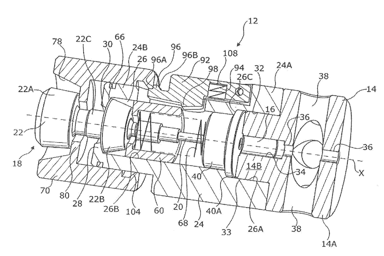
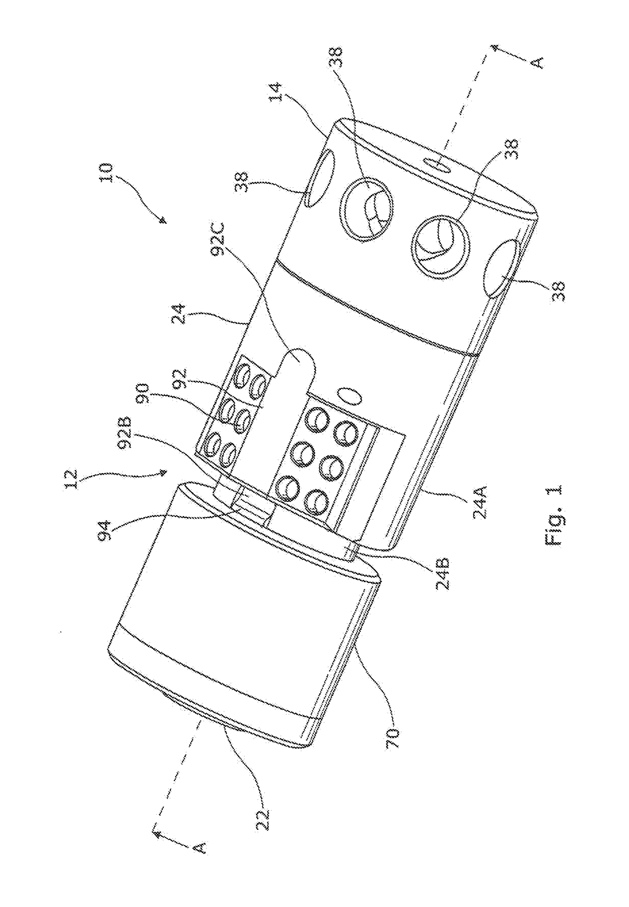
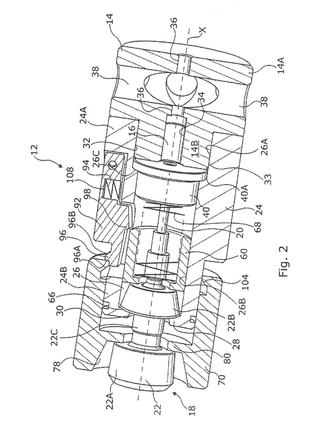
[0210]A grenade 10 Incorporating a firing mechanism 12 in accordance with a first embodiment of the present invention is shown in FIGS. 1 to 3D. The grenade 10 is a so-called stun grenade or distraction device and comprises a firing mechanism 12 and a munitions compartment 14 releasably mountable to the firing mechanism. The munitions compartment 14 holds a pyrotechnic cartridge 16 containing a primer charge, a fuze and a deflagrating pyrotechnic charge. The firing mechanism 12 has a firing system 18 including a firing pin 20 and an actuator 22 which is operative to move the firing pin 20 from an initial position ...


PUM


Abstract

A grenade firing mechanism (12) includes a body (24) containing a firing pin (20) and a tiring pin actuator mechanism (22). A safety system includes twist to arm collar (70) and a safety interlock (92). The collar is movable between an unarmed position and an armed position and tire safety interlock is movable between a collar locking position, a collar release position and a firing position. When the collar (70) is in the unarmed position and the safety interlock (92) is in the collar locking position, actuation of the firing pin (20) is inhibited and the safety interlock (92) inhibits movement of the collar to the armed position. When, the safety interlock (92) is in the collar release position, the collar (70) is able to be moved between said unarmed and armed positions and actuation of the firing pin is inhibited. When the collar (70) is in the armed position and the -safety interlock (92) is in the firing position, actuation of the firing pin is enabled.

Description

CROSS-REFERENCES TO RELATED APPLICATIONS[0001]This is a U.S. National Stage filing made pursuant to 35 U.S.C. § 371, This U.S. application claims the benefit of a prior Patent Cooperation Treaty filing that was assigned Application No, PCT / GB2016 / 051663. The earliest priority date in the parent application is Jun. 16, 2015.STATEMENT REGARDING FEDERALLY SPONSORED RESEARCH OR DEVELOPMENT[0002]Not Applicable.MICROFICHE APPENDIX[0003]Not ApplicableBACKGROUND OF THE INVENTION1. Field of the Invention[0004]The present invention relates to firing mechanisms for grenades.2. Description of the Related Art[0005]Grenades are known which contain a charge that is set off when the grenade is thrown. Grenades may contain, an explosive charge contained in a housing that fragments when the charge is detonated so as to cause physical harm to personnel and equipment in the vicinity. Also known are stun grenades, sometimes also referred to as diversionary devices or distraction devices that are general...

Claims


Application Information

Patent Timeline
IPC IPC(8): F42C15/00F42C14/02F42B27/00F42C15/44
CPCF42C15/005F42C14/02F42B27/00F42C15/44F42B8/26
Inventor THOMAS, DUNCAN
Owner ALS INC
Learn More