Crossing point detector, camera calibration system, crossing point detection method, camera calibration method, and recording medium

a detection method and cross-point technology, applied in the field of cross-point detectors and camera calibration methods, can solve the problem of low and achieve the effect of improving the detection precision of crossing points in checker patterns

Active Publication Date: 2018-05-24
PANASONIC INTELLECTUAL PROPERTY MANAGEMENT CO LTD
View PDF1 Cites 11 Cited by
  • Summary
  • Abstract
  • Description
  • Claims
  • Application Information

AI Technical Summary

Benefits of technology

[0007]According to the present disclosure, the detection precision of crossing points in a checker pattern can be improved. Additional benefits and advantages of the disclosed embodiments will become apparent from the specification and drawings. The benefits and / or advantages may be individually obtained by the various embodiments and features of the specification and drawings, which need not all be provided in order to obtain one or more of such benefits and / or advantages.

Problems solved by technology

However, with the technology cited above, there is a problem of low detection precision of crossing points in the checker pattern.

Method used


Image

  • Crossing point detector, camera calibration system, crossing point detection method, camera calibration method, and recording medium
  • Crossing point detector, camera calibration system, crossing point detection method, camera calibration method, and recording medium
  • Crossing point detector, camera calibration system, crossing point detection method, camera calibration method, and recording medium

Examples


embodiment 1

Summary of Embodiment 1

[0114]The above thus describes the crossing point detector 101 and the crossing point detection method according to Embodiment 1. To summarize, the crossing point detector 101 includes the configuration illustrated in FIG. 10A, and the crossing point detection method is indicated by the flowchart illustrated in FIG. 10B.

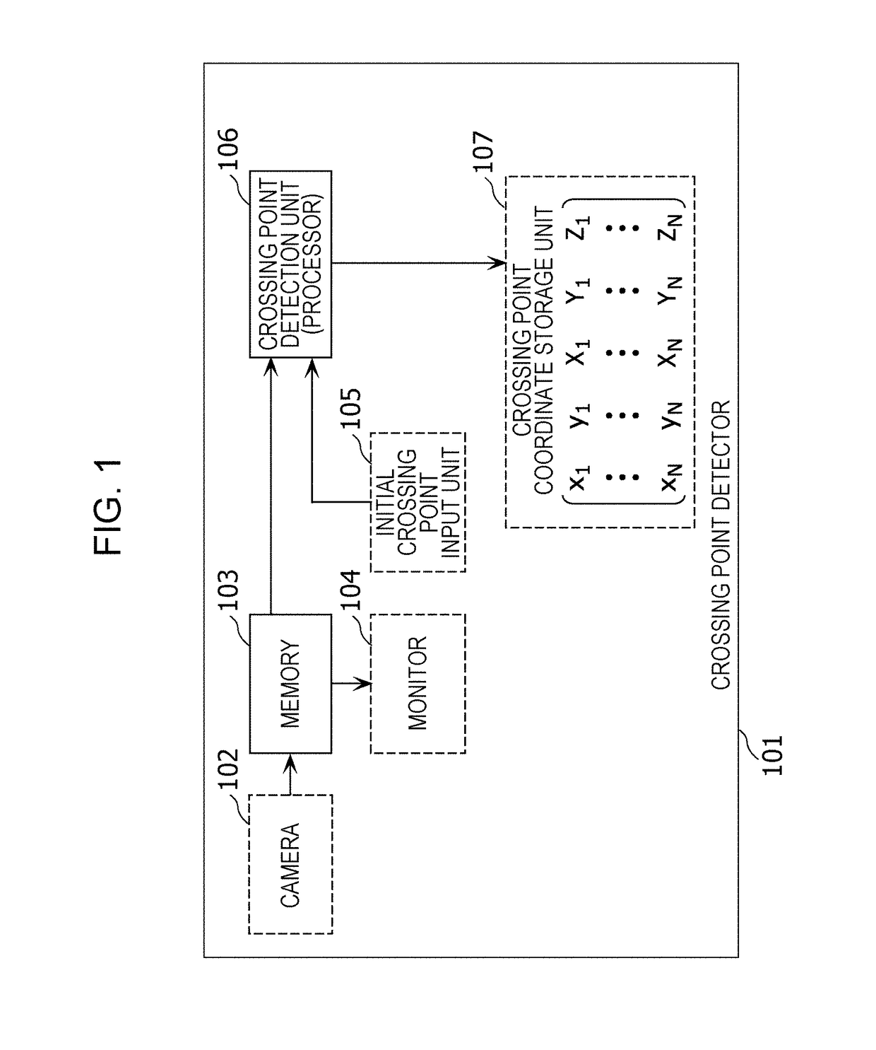
[0115]FIG. 10A is a block diagram illustrating a configuration of the crossing point detector 101 according to a first aspect of the present disclosure.

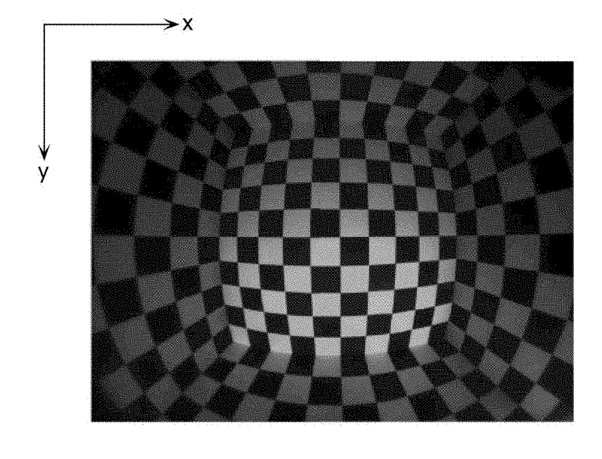
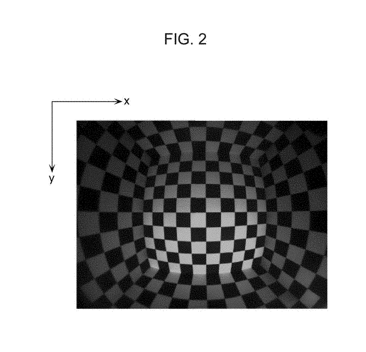
[0116]The crossing point detector 101 is provided with memory 103 and a processor 106. The memory 103 stores the captured image obtained by the imaging of a checker pattern. The processor 106 reads out at least a partial image of the captured image from the memory 103 as the image to process. Subsequently, the processor 106 detects a crossing point of two boundary lines in the checker pattern depicted in the image to process.

[0117]Herein, each of the two boundary lines is a boundary line between...

embodiment 2

Summary of Embodiment 2

[0160]The above thus describes the crossing point detector 1101 and the crossing point detection method according to Embodiment 2. To summarize, the crossing point detector 1101 includes the configuration illustrated in FIG. 22A, and the crossing point detection method is indicated by the flowchart illustrated in FIG. 22B.

[0161]FIG. 22A is a block diagram illustrating a configuration of the crossing point detector 1101 according to a second aspect of the present disclosure.

[0162]The crossing point detector 1101 is provided with memory 103 and a processor 1102. The memory 103 stores the captured image obtained by the imaging of a checker pattern. The processor 1102 reads out at least a partial image of the captured image from the memory 103 as the image to process. Subsequently, the processor 1102 detects a crossing point of two boundary lines in the checker pattern depicted in the image to process.

[0163]Herein, each of the two boundary lines is a boundary line...

embodiment 3

Coarse-to-Fine Search in Crossing Point Detection

[0172]As described above, in the case of detecting crossing points with a function model, the calculation cost is low because a gradient method is usable. On the other hand, in the case of detecting crossing points with a numerical model, the calculation cost is high because a gradient method is unusable, but crossing points can be detected with higher precision.

[0173]Accordingly, the crossing point detector 1101 according to the present embodiment has a configuration similar to the crossing point detector 1101 according to Embodiment 2, but the crossing point detection unit 1102 according to the present embodiment is additionally provided with the functions of the crossing point detection unit 106 according to Embodiment 1. In other words, the crossing point detection unit 1102 according to the present embodiment computes the position of a crossing point with a function model as a first initial position, similarly to Embodiment 1. Ne...


PUM


Abstract

A crossing point detector includes memory and a crossing point detection unit that reads out a square image from a captured image in the memory, and detects a crossing point of two boundary lines in a checker pattern depicted in the square image. The crossing point detection unit decides multiple parameters of a function model treating two-dimensional image coordinates as variables, the parameters optimizing an evaluation value based on a difference between corresponding pixel values represented by the function model and the square image, respectively, and computes the position of a crossing point of two straight lines expressed by the decided multiple parameters to thereby detect the crossing point with subpixel precision. The function model uses a curved surface that is at least first-order differentiable to express pixel values at respective positions in a two-dimensional coordinate system at the boundary between black and white regions.

Description

BACKGROUND1. Technical Field[0001]The present disclosure relates to a crossing point detector, a camera calibration method, and the like that detect crossing points in a checker pattern from a captured image depicting the checker pattern.2. Description of the Related Art[0002]To calibrate a camera such as a vehicle-mounted camera, it is necessary to associate positions in three-dimensional space, or in other words positions in a three-dimensional coordinate system, with pixel positions in a captured image obtained by imaging with a camera. For this objective, in the related art, a crossing point detector uses a camera to image a checker pattern having a known shape. Subsequently, the crossing point detector detects crossing points in the checker pattern depicted in the captured image, and thereby associates positions in a three-dimensional coordinate system with pixel positions in the captured image (for example, see Japanese Unexamined Patent Application Publication Nos. 2011-18808...

Claims


Application Information

Patent Timeline
Patent Type & Authority Applications(United States)
IPC IPC(8): G06T7/80G06T7/73H04N5/232G06T7/13
CPCG06T7/80G06T7/75H04N5/23293G06T7/13G06T2207/20164H04N23/63G06T2207/30208G06T2207/30244H04N17/002
Inventor WAKAI, NOBUHIKOAZUMA, TAKEONOBORI, KUNIOSATOMARUYAMA, AYAKO
Owner PANASONIC INTELLECTUAL PROPERTY MANAGEMENT CO LTD
Why Eureka
Try Eureka