Landing bearing assembly and rotary machine equipped with such an assembly

a technology of rotary machines and bearings, which is applied in the direction of bearings, shafts, dynamo-electric machines, etc., can solve the problems of low load capacity of auxiliary bearings, too high compression forces on balls, partial or total destruction of auxiliary bearings, etc., and achieve the effect of keeping some elasticity

Active Publication Date: 2018-05-31
SKF MAGNETIC MECHATRONICS
View PDF3 Cites 4 Cited by
  • Summary
  • Abstract
  • Description
  • Claims
  • Application Information

AI Technical Summary

Benefits of technology

[0014]Thanks to the invention, in the event of a heavy shock which typically lasts not more than one second, upon landing of the rotor, a part of the mechanical energy of the shock is first absorbed by the compliance ring which deforms elastically. Should there be a remaining amount of energy, it is then absorbed by the emergency landing ring when the latter contacts the shaft of the rotor, so that the compliance ring is not further compressed and keeps some elasticity so as to protect the auxiliary rolling bearing from too high compression forces.
[0015]Thanks to the invention, once the shock ends, the rotation of the shaft of the rotor can come to a full stop with the preserved auxiliary rolling bearing, or even continue to run without any damage on the mechanical parts.

Problems solved by technology

The rolling elements of the auxiliary rolling bearing are usually balls because they offer a higher possible rotational speed than rollers, but unfortunately also a lower load capacity for the auxiliary bearing.
However, in some applications, the rotary machine may be subject to much higher shocks created in the environment of the rotary machine, such as a handling shock or a military shock, resulting in too high compression forces on the balls and possibly the partial or total destruction of the auxiliary bearing, if not of the rotary machine itself, when the above mentioned patent would not prevent contact and damage to unwanted part inside the machine.

Method used


Image

  • Landing bearing assembly and rotary machine equipped with such an assembly
  • Landing bearing assembly and rotary machine equipped with such an assembly
  • Landing bearing assembly and rotary machine equipped with such an assembly

Examples


Embodiment Construction

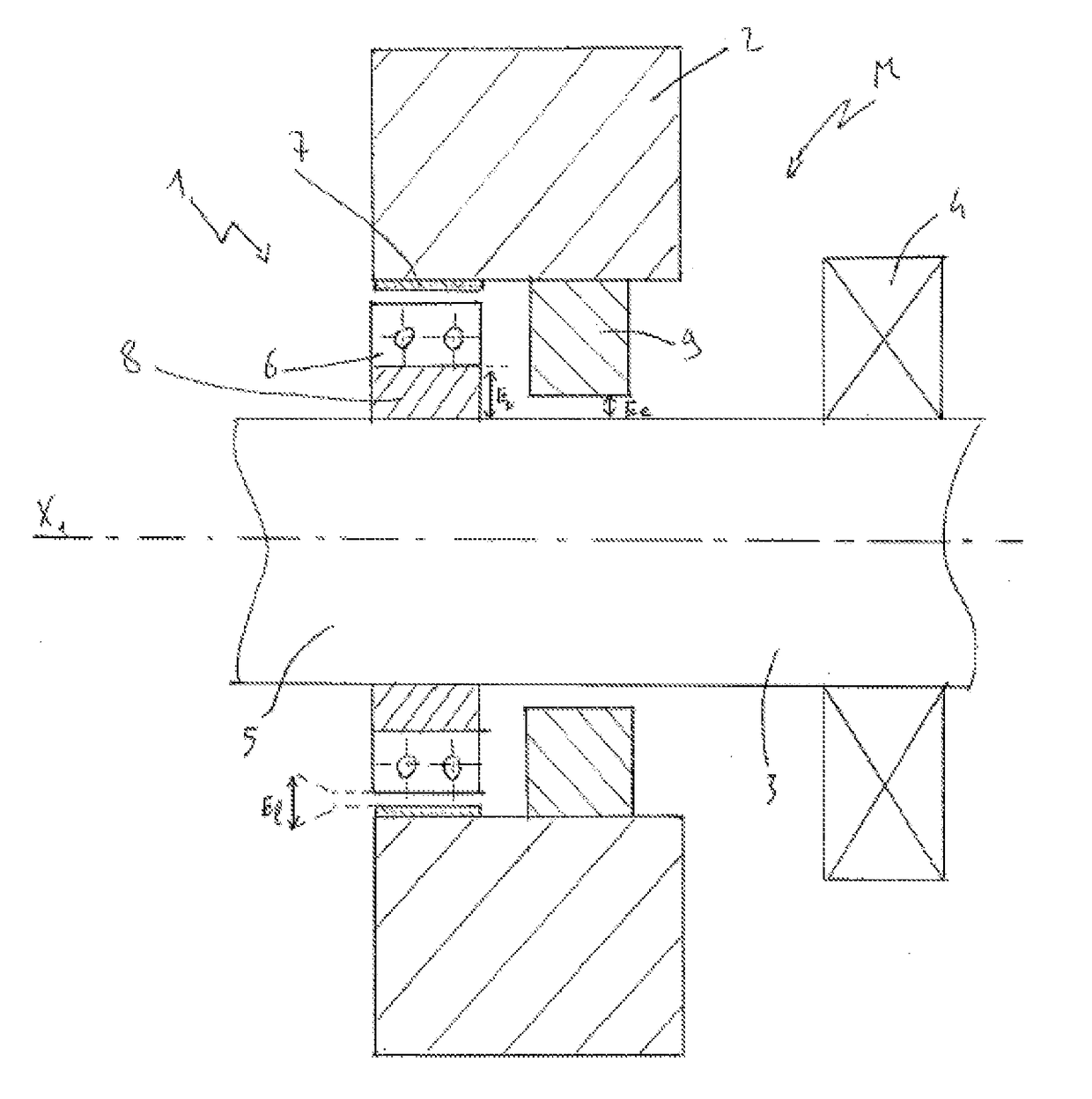
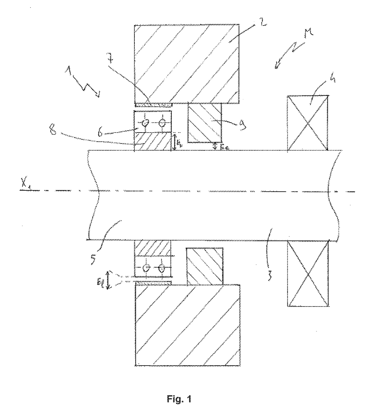
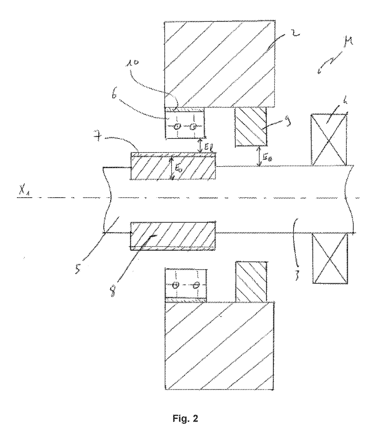
[0032]FIGS. 1 to 3 show a rotary machine M centered on a central axis X1.

[0033]In what follows, a radial direction designates a direction perpendicular to the central axis X1, and an axial direction a direction parallel to the central axis X1.

[0034]The rotary machine M comprises a stator 2, a rotor 3, a magnetic bearing 4, and a landing bearing assembly 1.

[0035]The stator 2 is radially around the rotor 3 which is rotatable around central axis X1. The rotor 3 comprises a shaft 5.

[0036]The magnetic bearing 4 is schematically represented on the figures, its arrangement relative to the stator 2 and the rotor 3 being not shown, for simplification purpose. The magnetic bearing may consist of a radial magnetic bearing, an axial magnetic bearing, or a combination of at least one radial magnetic bearing and one axial magnetic bearing. The magnetic bearing is preferably of the active type.

[0037]The landing bearing assembly 1 supports the rotor 3 essentially during a starting or stopping opera...


PUM


Abstract

A landing bearing assembly for a rotary machine rotatable around a central axis and having a stator, a rotor with a shaft, a magnetic bearing, an auxiliary rolling bearing with two lateral faces, a landing sleeve facing, in normal operation of the rotary machine when the rotor is supported only by the magnetic bearing, the auxiliary rolling bearing at a nominal distance defined as the landing airgap El, the auxiliary rolling bearing coming into contact with the landing sleeve upon landing of the rotor in the event of a high shock. The assembly further provides a compliance ring with a nominal thickness Eo made from a material with a lower mechanical stiffness than the material constituting the other components of the landing bearing assembly to first absorb some energy of the shock by elastic deformation resulting in a reduction of its thickness.

Description

CROSS-REFERENCE[0001]This application claims priority to European patent application no. 16306564.2 filed on Nov. 28, 2016, the contents of which are fully incorporated herein by reference.TECHNOLOGICAL FIELD[0002]The invention concerns a landing bearing assembly to be used in a rotary machine comprising a rotor, a stator and a magnetic bearing. The invention also relates to a rotary machine comprising a landing bearing assembly.BACKGROUND[0003]Some conventional rotary machines are equipped with a stator, a rotor, and a magnetic bearing for supporting without contact the rotation of the rotor with respect to the stator. In order to avoid any direct contact between the stator and the rotor in case of failure, shutdown or overload of the magnetic bearing, which may lead, in the worst case, to the destruction of the machine when rotating at high speed, an auxiliary rolling bearing is arranged on the stator and a landing sleeve is arranged on the rotor. Upon landing of the rotor that is...

Claims


Application Information

Patent Timeline
Patent Type & Authority Applications(United States)
IPC IPC(8): F16C39/02F16C32/04H02K7/09
CPCF16C39/02F16C32/0425H02K7/09F16C32/0406F16C27/04F16C32/0442F16C2380/26H02K7/083
Inventor BAUDELOCQUE, LUC
Owner SKF MAGNETIC MECHATRONICS
Why Eureka
Try Eureka