Terminal cover
a terminal cover and cover body technology, applied in the direction of supporting/enclosed/cases, electrical devices, dynamo-electric machines, etc., can solve the problems of mechanical scraping of the terminal cover, increased size, and complicated structure, so as to facilitate elastic deformation of the cover body, reduce the risk of physical interference with other parts, and increase the size of the curved portion
- Summary
- Abstract
- Description
- Claims
- Application Information
AI Technical Summary
Benefits of technology
Problems solved by technology
Method used
Image
Examples
first embodiment
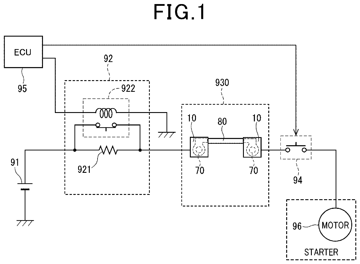
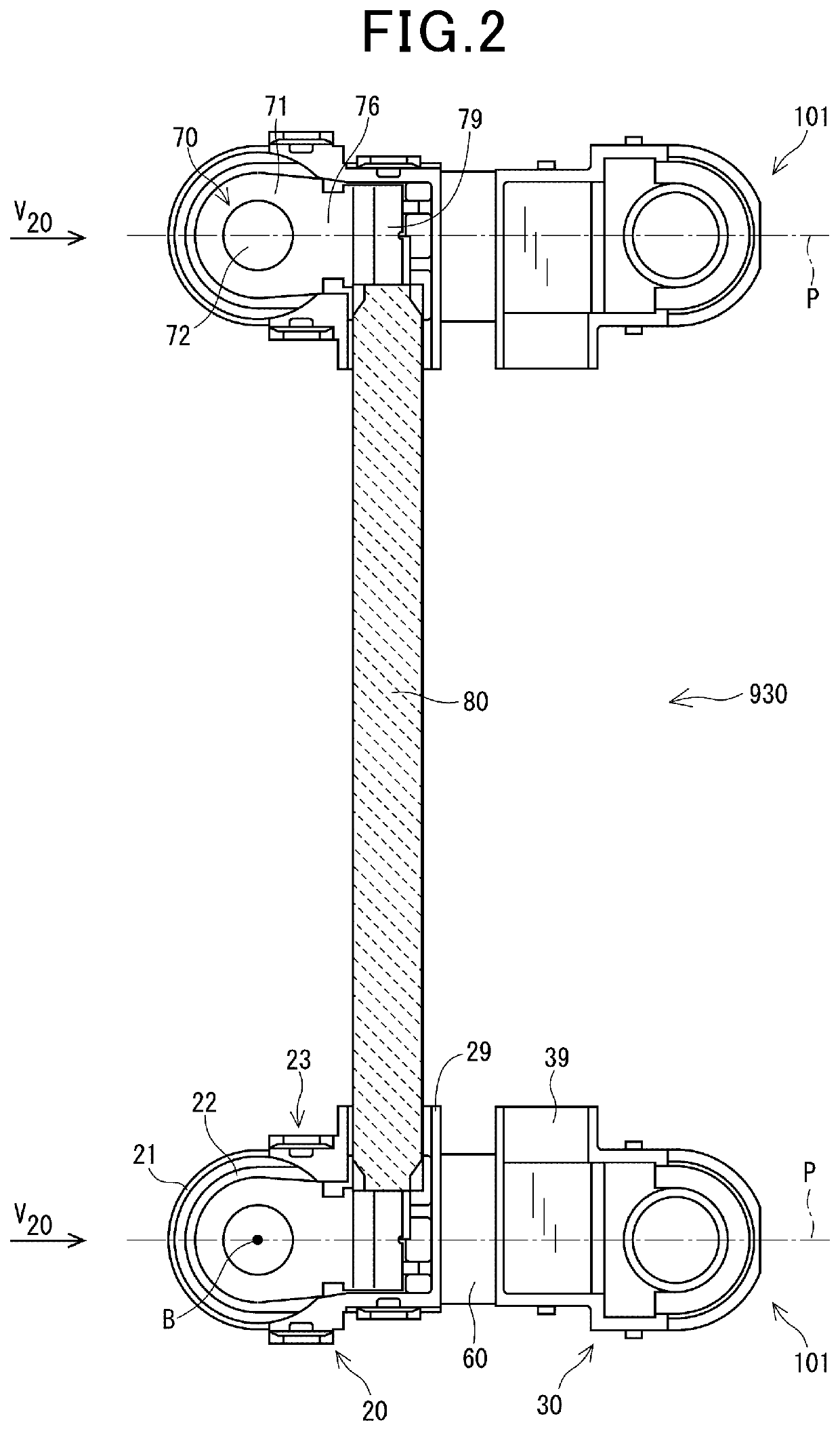
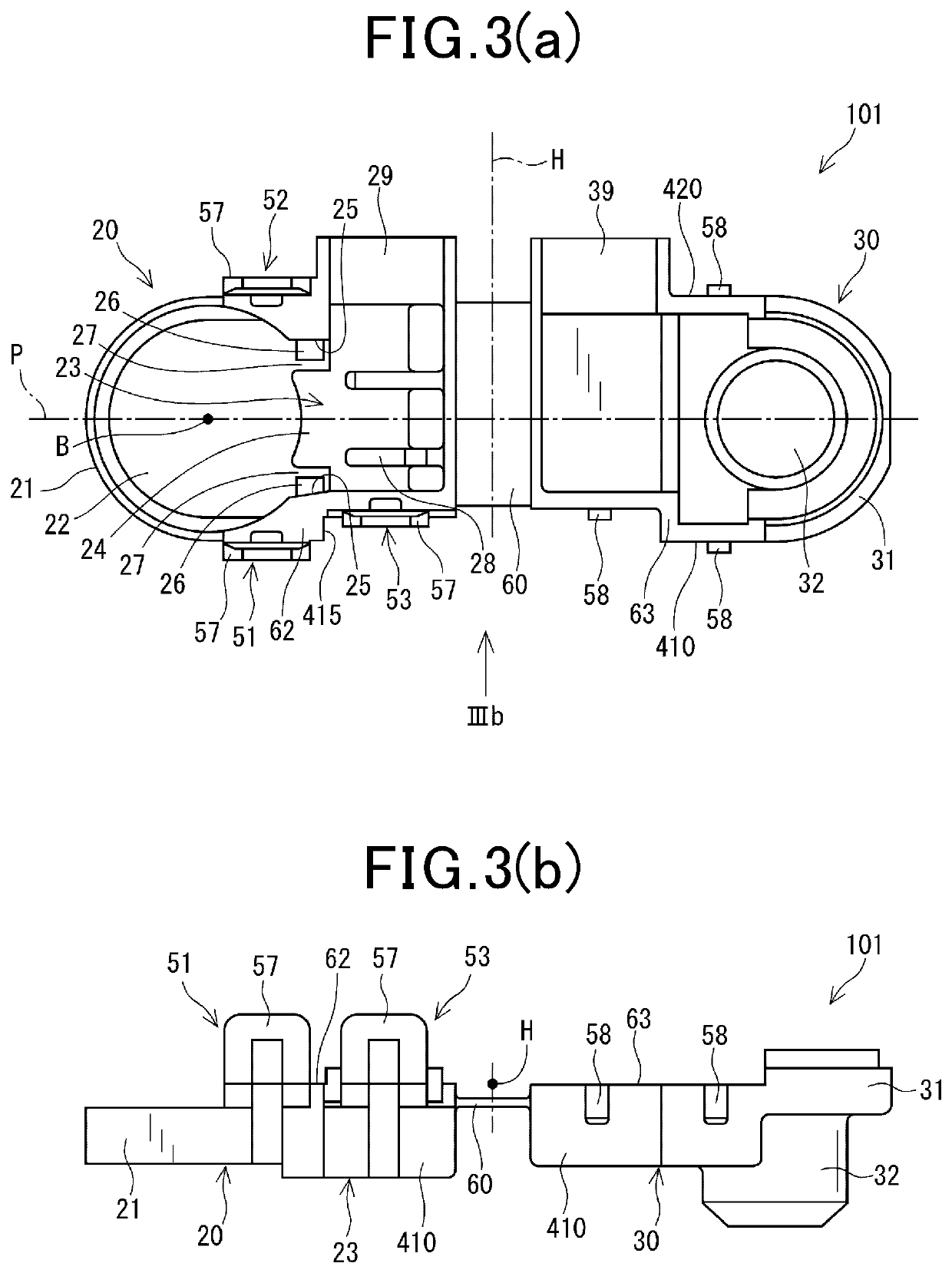
[0036]The first embodiment will be described below with reference to FIGS. 2 to 8. FIG. 2 illustrates an entire structure of the terminal cover-wire subassembly 930 when the lid 30 is opened. In FIG. 2, the two terminal covers 101 are illustrated as being mounted on upper and lower ends of the electrical wire 80. An alternate long and short dash line extending horizontally through each of the terminal covers 101 represents an imaginary reference plane P whose definition will be discussed later in detail. Each of the terminal covers 101 in the first embodiment includes the wire retainer 29 which holds the electrical wire 80 so as to extend in a direction perpendicular to the reference plane P.
[0037]Specifically, when viewed in the direction V20 in FIG. 2, an upper one of the terminal covers 101 (which will also be referred to below as an upper terminal cover) has the wire retainer 29 located on the right side of the reference plane P, while a lower one of the lower terminal covers 10...
second and third embodiments
[0066]The second and third embodiment which are different in number or layout of claws from the first embodiment will be described below with reference to FIGS. 9(a) and 9(b). FIG. 9(a) illustrates the terminal cover 102 according to the second embodiment. The terminal cover 102 has a pair of claws 267 arranged on an inner wall of the curved portion 21. The claws 267 are diametrically opposed to each other across the reference plan P, i.e., the center B of the open hole 22. The claws 267 retain portions of the bolt seat 71 of the terminal 70 which are diametrically opposed to each other in the width-wise direction of the terminal 70 without physical interference with a head of a bolt indicated by an alternate long and short dash line. When the terminal 70 is installed in the terminal cover 102, the curved portion 21 is flexed to increase the interval between the claws 267, so that the terminal 70 passes the claws 267 and is then retained by the claws 267.
[0067]FIG. 9(b) illustrates ...
fourth embodiment
[0068]FIG. 10 illustrates the terminal covers 104 according to the fourth embodiment which is different in orientation of the terminal covers 104 relative to the electrical wire 80 from the first embodiment. FIG. 10 shows the terminal cover-wire subassembly 930. The electrical wire 80 is joined to the wire connectors 794 of the terminal covers 104. Each of the wire connectors 794 is aligned with the axial direction of a corresponding one of the terminals 704. In other words, the electrical wire 80 is joined to the terminal covers 104 with a length thereof extending in the axial direction of the terminals 704. Each of the terminal covers 104 is formed only by the cover body 20. In other words, the terminal cover 104 is not equipped with the hinge 60 and the lid 30 in the first embodiment. The structure of the terminal cover 104 offers the beneficial advantages A) and B) described above.
[0069]The terminal cover 104 may alternatively be equipped with a lid with no hinge which closes th...
PUM
 Abstract
Description
Claims
Application Information
 - R&D
- Intellectual Property
- Life Sciences
- Materials
- Tech Scout
- Unparalleled Data Quality
- Higher Quality Content
- 60% Fewer Hallucinations
Browse by: Latest US Patents, China's latest patents, Technical Efficacy Thesaurus, Application Domain, Technology Topic, Popular Technical Reports.
© 2025 PatSnap. All rights reserved.Legal|Privacy policy|Modern Slavery Act Transparency Statement|Sitemap|About US| Contact US: help@patsnap.com


