Crushing shell with rotational lock

a technology of rotation lock and crushing shell, which is applied in the direction of grain treatment, etc., can solve the problems of weakening the topshell, and affecting the operation of the topshell

Active Publication Date: 2018-06-14
SANDVIK INTELLECTUAL PROPERTY AB
View PDF7 Cites 0 Cited by
  • Summary
  • Abstract
  • Description
  • Claims
  • Application Information

AI Technical Summary

Benefits of technology

[0020]The extractor is advantageous to initiate the axial pushing of the crushing shell from the topshell that is often difficult following extended use of the crusher as the crushing shell becomes fused to the topshell due to the compressive crushing forces.

Problems solved by technology

However, conventional arrangements are disadvantageous for a number of reasons.
In particular, the upper and / or lower annular rims of the topshell are typically subjected to significant loading forces as the topshell is mated against additional components within the crusher such as a spider and the bottom shell.
Removing excessive material from the respective topshell upper and lower rims to accommodate locking attachments that engage the crushing shell can weaken the topshell and increases the likelihood of stress concentrations and fracture propagation.
It is not uncommon for such bolts to shear during use resulting in the concave rotating within the topshell and in some instances falling into the bottom shell and damaging further components of the crusher.

Method used


Image

  • Crushing shell with rotational lock
  • Crushing shell with rotational lock
  • Crushing shell with rotational lock

Examples


Embodiment Construction

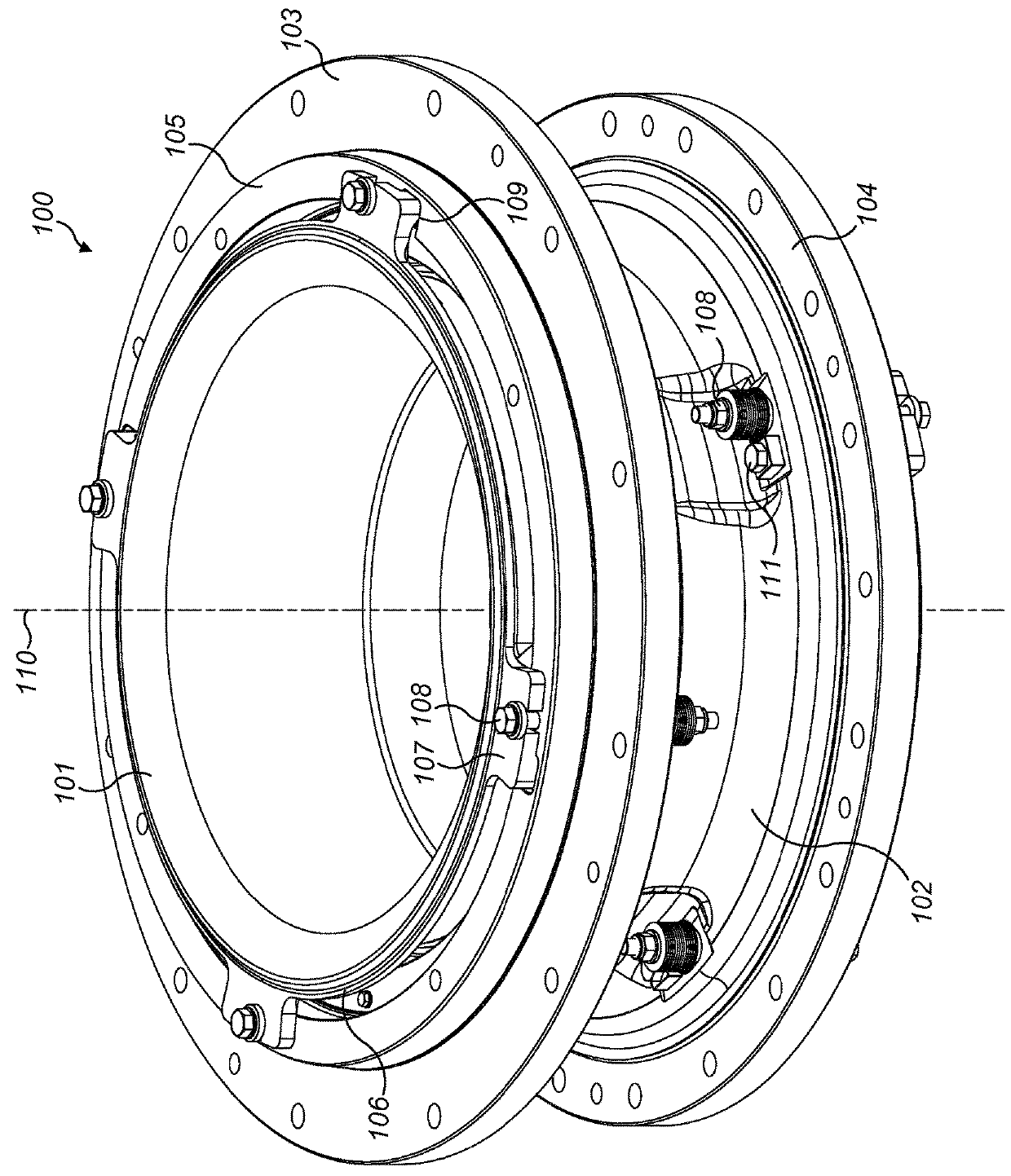
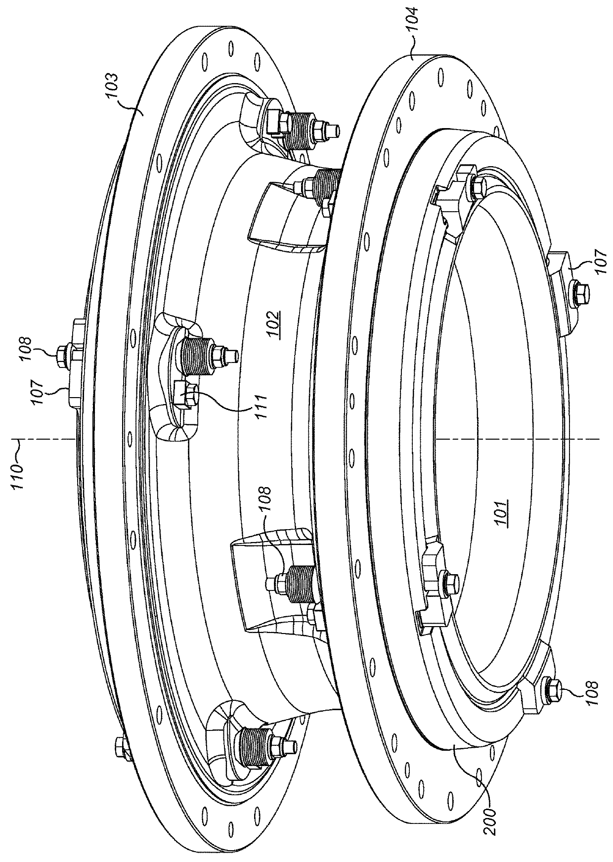
[0030]Referring to FIGS. 1 and 2, shell assembly 100 comprises a topshell indicated generally by reference 102 having a generally annular configuration extending around central axis 110. Topshell 102 comprises an upper annular rim 103 separated axially from a lower annular rim 104. An annular tapper-fit collar 105 projects axially from a radially inner region of upper annular rim 103 and a corresponding tapper-fit collar 200 projects axially from lower annular rim 104. Collar 105 and rim 103 provide a mounting for a crusher spider (not shown) representing an upper region of the gyratory crusher. Similarly, lower annular collar 200 and rim 104 provide regions for mounting top shell 102 on a corresponding bottom shell (not shown) of the crusher. As with conventional topshell configurations, collars 105, 200 comprise a radial thickness being less than the respective rims 103, 104.

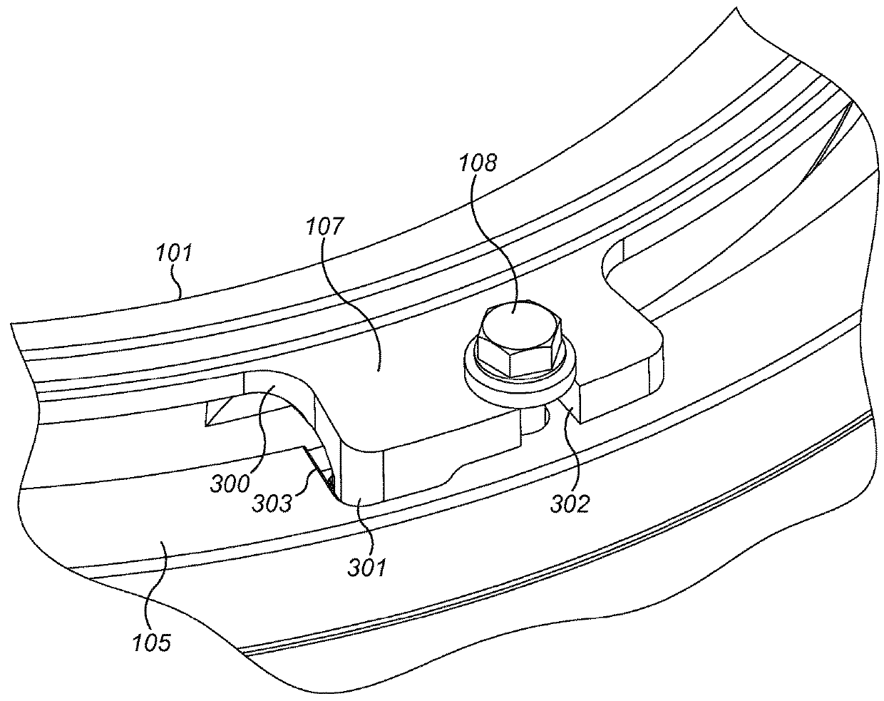
[0031]Assembly 100 comprises a first outer crushing shell (concave) 101 secured at topshell 102 via rim 103...


PUM


Abstract

A gyratory crusher shell has an annular wall extending around a longitudinal axis. A plurality of ears project radially outward from an annular rim of the topshell with each ear including a respective lug to sit within a corresponding recess at an annular rim of the topshell to rotatably lock the crushing shell at the topshell.

Description

FIELD OF INVENTION[0001]The present invention relates to a gyratory crusher topshell and a topshell assembly in which the crushing shell is axially and rotatably locked within the topshell via a plurality of ears and lock lugs projecting from the shell.BACKGROUND ART[0002]Gyratory crushers are used for crushing ore, mineral and rock material to smaller sizes. Typically, the crusher comprises a crushing head mounted upon an elongate main shaft. A first crushing shell (typically referred to as a mantle) is mounted on the crushing head and a second crushing shell (typically referred to as a concave) is mounted on a frame such that the first and second crushing shells define together a crushing chamber through which the material to be crushed is passed. A driving device positioned at a lower region of the main shaft is configured to rotate an eccentric assembly positioned about the shaft to cause the crushing head to perform a gyratory pendulum movement and crush the material introduced...

Claims


Application Information

Patent Timeline
Patent Type & Authority Applications(United States)
IPC IPC(8): B02C2/04B02C2/00
CPCB02C2/047B02C2/005B02C2/00B02C2/04B02C2/045B02C23/04
Inventor LARSSON, MIKAEL MHALLBERG, ANDERS
Owner SANDVIK INTELLECTUAL PROPERTY AB
Why Eureka
Try Eureka